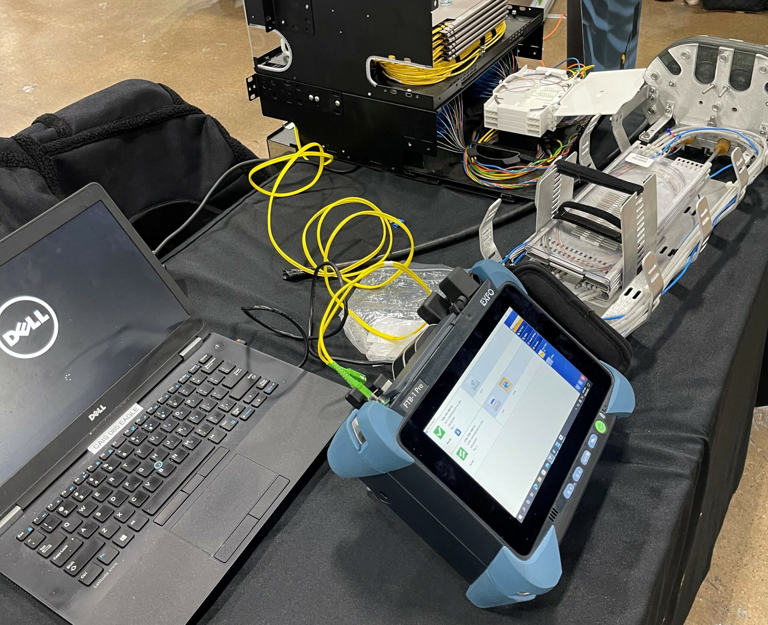
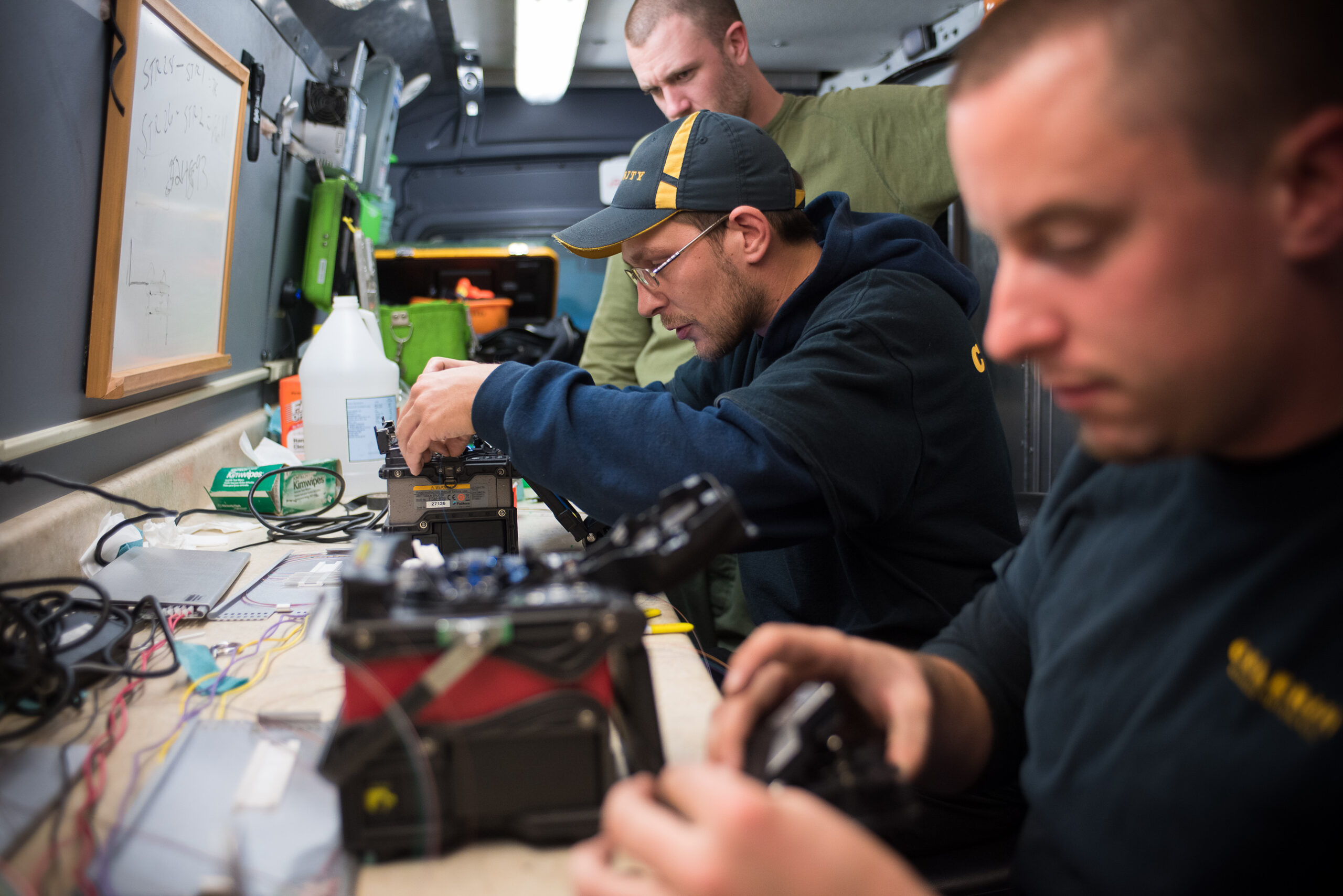
When deploying high-speed 100G and 400G networks, proper fiber characterization is mission critical. A single missed test can cause service failures, costly delays, and frustrated customers. Following the ITU-T G.650.3 standard ensures your fiber links meet the strict demands of next-generation systems.
Why 100G/400G Networks Require Stricter Fiber Characterization
Legacy 10G systems could handle minor imperfections, but 100G and 400G run on razor-thin margins. And in most cases, the majority of high-speed network failures stem from inadequate fiber characterization during the deployment phase.
400G networks use PAM4 modulation, requiring Optical Signal-to-Noise Ratio (OSNR) levels above 30 dB that are double of what 100G systems need. This leaves little room for error. Even a single bend in the fiber can lower performance below acceptable limits. Proper fiber characterization, however, helps avoid downtime, speeds up troubleshooting, and improves customer satisfaction.
Understanding ITU-T G.650.3 Requirements
G.650.3 is the international standard for testing installed single-mode optical fiber cable links. It sets consistent methods for measurement accuracy across global network deployments. For 100G and 400G networks, following this standard is what enables reliable performance.
The Essential G.650.3 Checklist for 100G/400G Turn-Ups
Phase 1: Pre-Testing Preparation
Before any field measurements begin, preparation is key to ensuring accurate and repeatable results under G.650.3. Phase 1 focuses on verifying equipment readiness, reviewing documentation, and confirming that all safety and technical requirements are in place. Laying this foundation helps prevent errors during testing and sets the stage for a successful 100G/400G turn-up. Things to consider include:
- Verify test equipment calibration (within 12 months)
- Confirm support for 1310nm, 1550nm, and 1625nm wavelengths
- Review link documentation and splice locations
- Check link budget calculations
- Confirm safety protocols
Phase 2: Physical Layer Inspection
With preparation complete, the next step is to verify the integrity of the physical layer. Phase 2 focuses on thorough connector inspection using high-magnification tools and international pass/fail standards. By cleaning, rechecking, and replacing any faulty connectors, technicians ensure a clean optical path that eliminates one of the most common causes of test failures and performance issues in 100G/400G networks. A single 2-5 μm dust particle, for example, can block the 9 μm core of single-mode fiber. At 400G, even tiny contamination can push OSNR below limits. Things to consider in this critical phase include:
- Inspect all connectors with a video microscope (minimum 400x)
- Apply IEC 61300-3-35 pass/fail rules
- Clean connectors, then re-inspect
- Replace damaged connectors
Phase 3: Insertion Loss Testing
Once the physical layer is confirmed clean, attention shifts to measuring signal performance. Phase 3 involves insertion loss testing at multiple wavelengths and in both directions, following G.650.3 best practices. By monitoring temperature, checking bidirectional consistency, and validating Optical Return Loss (ORL) thresholds, technicians ensure the link can support the demanding power and sensitivity requirements of 100G/400G transmission. Things to consider include:
- Test insertion loss at 1310nm, 1550nm, and 1625nm in both directions
- Record temperature during testing (fiber loss varies with temperature)
- Investigate if bidirectional difference >0.3 dB
- Test Optical Return Loss (ORL) using G.650.3 guidelines
- Confirm ORL values meet requirements (typically >28 dB for 100G/400G)
Phase 4: OTDR Characterization
After insertion loss testing verifies overall performance, Phase 4 provides a deeper look into the fiber link itself. Using OTDR characterization at multiple wavelengths, technicians can pinpoint splice quality, reflective events, and potential stress points that may impact long-term reliability. By documenting results and generating event maps, this step ensures a detailed baseline for both immediate validation and future maintenance of 100G/400G links. Things to consider include:
- Run bidirectional OTDR testing at all key wavelengths
- Use launch and receive cables (minimum 500m for long-haul links)
- Locate and measure all splice losses (should be <0.1 dB for fusion splices)
- Document reflective events and stress points
- Generate event maps for future maintenance reference
Phase 5: Dispersion Testing (Critical for 100G/400G)
Phase 5 of G.650.3 validation focuses on dispersion, a critical factor for high-speed transmission. Phase 5 testing measures both chromatic dispersion (CD) and polarization mode dispersion (PMD) to confirm the fiber can support 100G and 400G data rates. By validating tolerances across the C-band and ensuring mean DGD values remain within strict limits, technicians safeguard against signal distortion that can degrade performance over long distances.
- For Chromatic Dispersion (CD): Test across C-band at 1nm steps
- 100G tolerance: ±50,000 ps/nm
- 400G tolerance: ±20,000 ps/nm
- For Polarization Mode Dispersion (PMD): Ensure mean Differential Group Delay (DGD) values meet requirements:
- 100G: <10 ps mean DGD
- 400G: <2.5 ps mean DGD
- Take multiple samples to account for variation
Phase 6: Advanced Characterization for 400G
As networks scale to 400G, advanced fiber characterization becomes essential to validate performance under real-world conditions. Phase 6 adds deeper testing for spectral attenuation to ensure the link can handle higher-order modulation formats. By checking for water peak absorption around 1383nm and confirming OSNR margins well above vendor thresholds, technicians provide the confidence needed for error-free transmission at ultra-high speeds. Things to consider include:
- Spectral Attenuation: Check for water peak absorption near 1383nm
Phase 7: Documentation and Reporting
Phase 7 ensures that all testing results translate into lasting value for network operations. This focuses on documentation and reporting, turning raw measurements into actionable records. By compiling pass/fail reports, archiving test data, updating network management systems, and training operations staff, this phase provides both accountability and a solid foundation for ongoing reliability of 100G/400G networks. Things to consider include:
- Create a full test report with pass/fail status
- Store all raw test data for future troubleshooting
- Update network documentation systems
- Provide training for operations teams
Common Pitfalls to Avoid in High-Speed Network Testing
When testing high-speed networks, certain pitfalls can compromise measurement accuracy if not carefully managed. Temperature fluctuations, for example, can shift dispersion by approximately 0.02 ps/nm/km per degree Celsius, making it essential to document environmental conditions during testing. Similarly, poor launch conditions including incorrect mode conditioning, insufficient cable length, or substandard connector quality can skew results and mask underlying issues.
Polarization Mode Dispersion (PMD) is highly sensitive to environmental factors, so multiple samples are necessary to capture true network performance. Ignoring bidirectional differences can be misleading, as these often indicate connector defects, splice problems, or localized fiber stress that must be addressed to ensure reliable 100G/400G operation.
Professional Fiber Characterization ROI
Investing in professional G.650.3 fiber characterization delivers clear, measurable ROI for high-speed networks. By identifying potential issues early, it helps prevent up to 85% of fiber-related outages, significantly reducing downtime. Detailed baseline data accelerates troubleshooting and fault isolation, while maintaining proper fiber performance reduces stress on transceivers and extends equipment life. Comprehensive documentation supports SLA compliance and provides verifiable proof of network performance. Finally, thorough testing ensures the network is future-proofed, ready to accommodate upgrades and increased capacity without unexpected setbacks.
Successful 100G and 400G deployments depend on following the G.650.3 standard. Skipping steps or rushing testing puts your entire investment at risk. The investment in proper fiber characterization builds a reliable foundation for today’s bandwidth needs, and tomorrow’s move toward 800G networks and beyond.
Don't let inadequate testing compromise your high-speed network investment. By following this checklist, you ensure your network delivers the performance and reliability modern applications demand.
When to Use Professional Services
Certain network deployments demand specialized expertise beyond standard field testing. Specialized service providers bring advanced tools, proven methods, and decades of experience in high-speed fiber testing. Professional fiber characterization services are particularly valuable for submarine or ultra-long-haul links exceeding 1,000 km, as well as for dense wavelength division multiplexing (DWDM) systems where precision is critical. They are also recommended for networks with ultra-low latency requirements or mission-critical links governed by strict SLAs, ensuring both performance and reliability under the most demanding conditions. Especially consider when the following are in play:
- Submarine or ultra-long-haul links (>1,000km)
- Dense wavelength division multiplexing (DWDM) systems
- Networks with ultra-low latency requirements
- Mission-critical links with strict SLAs
Celerity: Trusted Partner in the Mid-Atlantic For Fiber Characterization
At Celerity, based in Quakertown, PA, we specialize in fiber characterization across the Mid-Atlantic region. With proven expertise, local knowledge, and a strong safety culture, we help utilities reduce downtime, improve grid reliability, and prepare for the future of smart energy. Want your 100G/400G network to succeed from day one? Celerity’s certified experts deliver G.650.3 fiber testing with proven accuracy and reliability. Contact us today for a consultation.


