The 400G Tipping Point: Why Your Fiber Planning Strategy Needs to Evolve Now
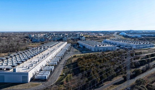
Data center operators in Ashburn and across the Mid-Atlantic are facing a bandwidth reality check. The migration from 100G to 400G is no longer a future consideration, it is happening in production environments today. What worked for legacy fiber infrastructure simply cannot support the signal integrity, distance requirements, and density demands of next generation networks.
The challenge is not just about faster speeds. It is about rethinking how fiber infrastructure is designed, validated, and maintained from the ground up. In our work with enterprise clients across Pennsylvania and Virginia, we have seen firsthand how improper Data Center Fiber Planning for 400G creates cascading failures that only appear after deployment, when the cost of remediation multiplies exponentially.
This guide walks through the critical elements of data center fiber planning that separate successful 400G deployments from expensive lessons learned. We will focus on three non-negotiable pillars: redundant path architecture, scalable physical infrastructure, and rigorous validation testing protocols.
Understanding 400G Fiber Requirements: The Technical Foundation
Before diving into planning methodology, you need to understand why 400G breaks traditional fiber assumptions. Unlike previous generations that relied on simple wavelength multiplexing, 400G implementations use advanced modulation schemes like PAM4 (Pulse Amplitude Modulation 4-level) that are far more sensitive to signal degradation.
Signal Integrity at Scale
PAM4 encoding doubles the bits per symbol compared to NRZ (Non-Return-to-Zero) used in 100G, but this efficiency comes at a cost. The signal-to-noise ratio requirements become exponentially more stringent. According to the Fiber Optic Association, 400G SR8 applications require eight parallel fibers transmitting at 50Gbps each, with maximum loss budgets as tight as 2.9dB for OM4 fiber over 100 meters.
This means your fiber plant must be pristine. A single contaminated connector or microbend in a trunk cable can push an entire 400G link beyond acceptable error rates. In practical terms, what passed as "good enough" for 100G will likely fail 400G characterization.
Distance and Modal Bandwidth Constraints
The IEEE 802.3cm standard defines 400G SR8 for short reach applications up to 100 meters on OM4 multimode fiber. For longer reaches, 400G DR4 (500m) and FR4 (2km) over single-mode fiber become necessary. This creates a critical planning decision point: do you invest in OM4/OM5 for short runs, or jump directly to single-mode for future flexibility?
Our recommendation for Ashburn data centers is to standardize on OS2 single-mode fiber for all new builds. While the initial cost is higher, it eliminates the distance limitations and provides a clear upgrade path to 800G and 1.6T without recabling. The Corning data center fiber guide confirms this approach, showing that single-mode fiber supports all current and foreseeable 400G/800G standards with minimal loss.
Redundancy Architecture: Designing for Five Nines Availability
Redundancy in 400G networks requires more than duplicate paths. It demands diverse physical routing, optical protection schemes, and intelligent failover mechanisms that operate at the wavelength level.
Physical Path Diversity
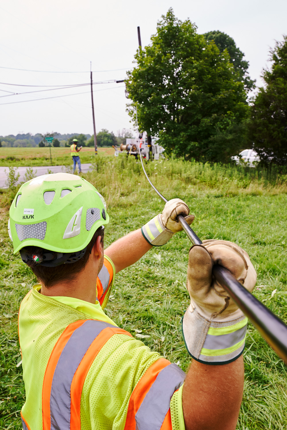
The first rule of Data Center Fiber Planning is never run redundant fibers through the same conduit or tray. True redundancy means physically separate paths from the MDA (Main Distribution Area) to each HDA (Horizontal Distribution Area). In Ashburn facilities, this often translates to routing one path under the raised floor and a second path through overhead cable trays.
We implemented this strategy for a financial services client in Northern Virginia where regulatory requirements demanded 99.999% uptime. By maintaining separate paths that never intersected, we isolated a construction incident that severed the underground path but left the overhead route intact, preventing a complete outage.
MESH Versus Spine-Leaf Considerations
While spine-leaf architecture dominates modern data center design, the fiber planning must support both primary and backup connectivity patterns. Each leaf switch needs dual homing to spine switches across diverse fiber paths. This creates a logical mesh over a physical star topology.
For 400G specifically, plan for breakout configurations where a 400G port splits into four 100G links. This provides operational flexibility but requires fiber counts that support both aggregated and discrete modes. Your cable plant should accommodate 16-fiber MPO connections for 400G SR8 while maintaining the ability to break out into duplex LC for 100G DR links.
Optical Protection Switching
Beyond physical diversity, implement optical protection switching at the transceiver level. Modern 400G coherent optics support Y-cable protection where a single transceiver receives signals from two diverse fibers and automatically switches to the backup path when the primary degrades. This happens in milliseconds, far faster than Layer 3 routing protocol convergence.
The ITU-T G.808.1 standard defines linear protection schemes that work exceptionally well for data center interconnects. We have deployed this for clients connecting Ashburn campuses across Route 7, where fiber cuts are a realistic risk. The protection switching occurs without dropping TCP sessions, maintaining application continuity.
Scalability Planning: Future-Proofing for 800G and 1.6T
Scalability in data center fiber planning means installing capacity you cannot use today but will need within three years. It is about balancing capital expenditure against operational agility.
Dark Fiber Strategy
The most cost-effective scalability approach is installing dark fiber during initial construction. Pre-terminating MPO cassettes with 24 or 32 fibers per rack unit, even if only a quarter are lit initially, provides massive expansion capacity. The incremental cost of the fiber itself is minimal compared to the labor of installation.
For a recent hyperscale deployment in Loudoun County, we installed 864-fiber count cables between each data hall, with only 96 fibers initially active. This represents a 9x growth capacity without additional construction. The Corning data center fiber guide validates this approach, recommending 40-60% overbuild for future growth.
High-Density Patching and Cabling
As fiber counts increase, physical management becomes critical. Use modular cassettes that support 1U densities of 96 or 144 fibers. Implement intelligent patching systems that can detect connection changes and update documentation automatically. This eliminates the manual record-keeping that fails at scale.
Standardize on polarity Method B for all MPO connections. This ensures consistent end-to-end connectivity regardless of how many patch panels the signal traverses. Polarity errors are the number one cause of 400G link failures we encounter during turn-ups.
Bandwidth Forecasting Models
Create a simple bandwidth forecasting model based on server refresh cycles. Most data centers replace servers every three to five years. Each new generation typically doubles network bandwidth requirements. If you are deploying 400G today, plan for 800G support when those servers refresh.
Track metrics like average and peak port utilization quarterly. When average utilization consistently exceeds 40% of port capacity, it is time to plan the next speed upgrade. This prevents the performance cliff that occurs when networks become congested.
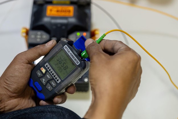
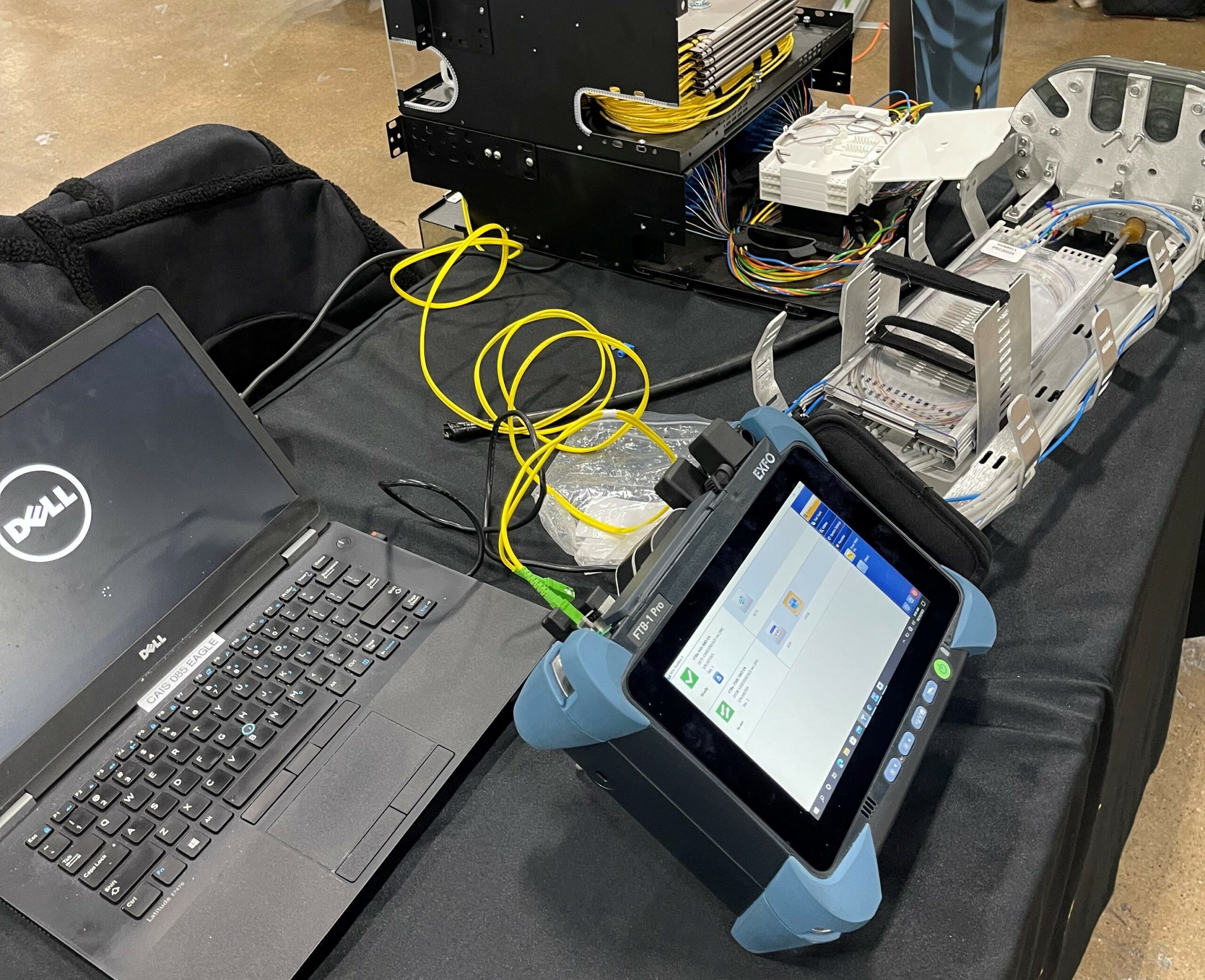
Next Generation Network Testing: Validation That Prevents Failures
Next Generation Network Testing for 400G is fundamentally different from previous generations. Simple insertion loss and OTDR tests are insufficient. You must validate the entire signal path under load conditions.
Fiber Characterization per G.650.3
The ITU-T G.650.3 standard defines comprehensive fiber characterization tests required for 400G and beyond. This includes:
- Bidirectional insertion loss and return loss measurements
- Chromatic dispersion testing
- Polarization mode dispersion analysis
- OTDR trace analysis with event dead zone characterization
We perform these tests for every fiber span during installation, not just spot checks. For a recent 400G deployment in Ashburn, we discovered 12 fibers out of 288 that met insertion loss specs but failed chromatic dispersion requirements. Those fibers would have caused intermittent errors under load that basic testing would miss.
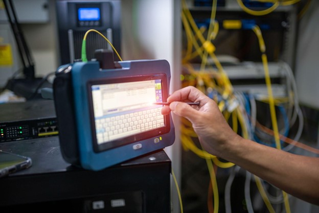
Load-Based Validation Testing
After fiber characterization, validate each 400G link under sustained load for 24 hours. Use test equipment that generates full line rate traffic with various packet sizes. Monitor for bit errors, latency spikes, and error correction events.
The key metric is pre-FEC (Forward Error Correction) bit error rate. Post-FEC errors are zero until the link fails completely. Pre-FEC errors indicate the link is operating on the edge of failure. We reject any link with pre-FEC BER worse than 1E-6, even though standards allow up to 2.4E-4. This conservative approach eliminates future failures.
Automated Test Documentation
Manual test documentation does not scale. Use test equipment that generates automated reports with pass/fail criteria and exports data to network management systems. This creates a digital twin of your fiber plant with historical performance data.
For enterprise clients, we provide a certification binder with every test result, fiber map, and as-built drawing. This documentation is essential for troubleshooting and proves compliance during audits. One client used our documentation to secure a $50 million cyber insurance policy, as it demonstrated due diligence in infrastructure validation.
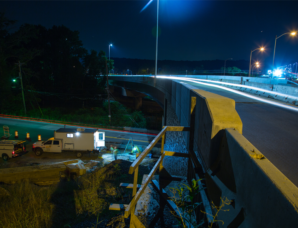
Ashburn-Specific Considerations: Building in the Data Center Capital
Ashburn, Virginia presents unique fiber planning challenges due to its concentration of data centers and existing infrastructure. The region's geology, utility coordination, and permitting requirements demand specialized approaches.
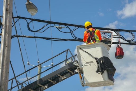
Utility Coordination and Permitting
Loudoun County requires detailed civil engineering plans for any underground fiber installation. Coordinate early with Dominion Energy and Verizon for pole attachments and conduit access. The permitting process typically takes 90 to 120 days, so factor this into project timelines.
We have established relationships with local utilities that accelerate this process. For a recent project along Waxpool Road, our pre-existing joint use agreements cut permitting time in half compared to new entrants.
Geological Factors
Ashburn's soil composition requires specific burial depths and conduit types. The clay-heavy soil retains moisture, increasing the risk of water infiltration. Use HDPE conduit with gel-filled innerducts and maintain minimum 36-inch burial depths for backbone routes.
During horizontal directional drilling, conduct potholing every 100 feet to verify existing utilities. The density of underground infrastructure in Ashburn makes utility strikes a significant risk. Our crews use ground-penetrating radar to map unknown utilities before drilling.
Inter-Campus Connectivity
Many Ashburn enterprises operate multiple data halls or campuses across different buildings. Plan for campus-wide fiber rings that provide redundant paths between facilities. Use 288-count or higher fiber cables for these rings, as they become the backbone for all inter-site traffic.
For one client with three campuses along Loudoun County Parkway, we designed a protected fiber ring with sub-2ms failover between any two points. This supports synchronous replication for their mission-critical applications.
Implementation Roadmap: From Planning to Production
Successful 400G fiber planning follows a phased approach that validates each decision before committing capital.
Phase 1: Assessment and Design (Weeks 1-4)
Conduct a comprehensive audit of existing fiber infrastructure. Test every strand for 400G compatibility, not just current utilization. Document all pathways, conduits, and spaces. Create a detailed design that includes capacity forecasts for three, five, and seven years.
Phase 2: Pilot Deployment (Weeks 5-8)
Install and test a single 400G link end-to-end. This reveals real-world issues with connector cleanliness, polarity, and signal integrity. Use this pilot to refine installation procedures and test protocols. We never skip this phase, as it prevents repeating mistakes across the entire data center.
Phase 3: Full-Scale Rollout (Weeks 9-20)
Execute the installation in logical segments, typically by data hall or row. Test and document each segment before moving to the next. This isolates issues and provides incremental capacity that can support production workloads.
Phase 4: Documentation and Handoff (Weeks 21-24)
Create final as-built documentation, test reports, and maintenance procedures. Train operations staff on 400G-specific troubleshooting techniques. Establish baseline performance metrics for ongoing monitoring.
ROI and Business Justification
The business case for proper 400G fiber planning extends beyond simple bandwidth increases. It reduces operational risk, lowers total cost of ownership, and enables revenue-generating services.
Risk Mitigation Value
A single 400G link failure can cost $10,000 per minute in lost revenue for high-frequency trading or e-commerce applications. Proper fiber planning reduces outage probability by over 90%. For one financial client, our redundant fiber design prevented an estimated $2 million loss during a construction cut.
Total Cost of Ownership
While 400G optics cost more per port, they reduce switch and cabling requirements by 75% compared to equivalent 100G solutions. A single 400G port replaces four 100G ports, reducing power, cooling, and rack space. Over a five-year lifecycle, this typically saves 30% on network infrastructure costs.
Service Enablement
400G infrastructure enables new revenue streams like AI training clusters, high-performance computing as a service, and low-latency financial exchange connectivity. These services command premium pricing and differentiate data center offerings. Without proper fiber planning, these opportunities remain out of reach.
Conclusion: The Time to Plan is Now
Data Center Fiber Planning for 400G and beyond is not an incremental upgrade. It requires a fundamental rethinking of how fiber infrastructure is designed, tested, and maintained. The technical requirements are more stringent, the business stakes are higher, and the margin for error is smaller.
Organizations that treat 400G as simply faster optics will face expensive remediation and operational instability. Those that invest in proper planning, redundant architectures, and comprehensive testing will gain a competitive advantage through superior reliability and scalability.
In Ashburn and other data center hubs, the difference between success and failure often comes down to execution details: connector cleanliness, polarity management, and thorough validation. These are not glamorous topics, but they determine whether your 400G network performs as designed or becomes a source of chronic problems.
The fiber you install today will likely remain in place for 15 to 20 years. Make decisions that support not just 400G, but the 800G and 1.6T networks that will follow. The incremental cost of future-proofing is minimal compared to the expense of replacing inadequate infrastructure.
Your Next Generation Network Testing protocol is your insurance policy. It is the difference between assuming your fiber plant is ready for 400G and knowing it with certainty. In our experience, this confidence is what separates leading data centers from those constantly fighting fires.