September 30, 2026

Advantages and Disadvantages of Horizontal Directional Drilling (HDD)

Installing underground utilities used to mean one thing: dig a trench, lay the pipe, fill it back in. That approach works in open fields. But what happens when a fiber route crosses a four-lane highway, a protected wetland, or a busy downtown intersection?

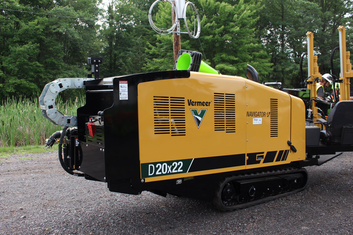
That is where horizontal directional drilling comes in. Horizontal directional drilling, commonly called HDD, is a trenchless construction method that installs conduit, cable, and pipe underground without cutting open the surface. A steerable drill head bores a path beneath obstacles, and crews pull the product back through the completed hole.

For telecom infrastructure projects, HDD has become a go-to solution, and the Fiber Broadband Association identifies directional boring as one of the primary underground construction techniques used in US fiber builds. Global Industry Analysts valued the global HDD market at $10.8 billion in 2024 and projects it will reach $16.4 billion by 2030, a 7.2% compound annual growth rate, driven by aging underground utility replacement, broader infrastructure development, and demand for minimally invasive installation methods 

But HDD is not the right fit for every project. Understanding both the advantages and disadvantages helps infrastructure planners make smarter decisions.

What Is Horizontal Directional Drilling?

Horizontal directional drilling is a steerable, trenchless method for installing underground utilities. Unlike traditional open-cut trenching, HDD keeps the surface intact by boring a path beneath roads, waterways, and existing infrastructure.

The process follows three main stages:

  1. Pilot hole drilling: A drill rig pushes a steerable drill head along a planned path, guided by electronic locating equipment. Entry angles typically range from 8 to 20 degrees.
  2. Reaming: Once the pilot hole reaches the exit point, crews pull back progressively larger cutting tools called reamers to enlarge the bore to the required diameter.
  3. Pullback: The product pipe, conduit, or cable bundle is attached to the drill string and pulled back through the enlarged bore to its final position.

This method allows installation of fiber optic cables, telecom conduit, water lines, gas pipes, and electrical cables with minimal surface disruption.

Advantages of Horizontal Directional Drilling

HDD offers several benefits that make it a strong choice for telecom and utility projects, especially in challenging environments.

Minimal Surface Disruption

  • The most significant advantage of HDD is what it does not do: tear up the ground. Roads, sidewalks, parking lots, and landscaping remain largely untouched. Crews only need small entry and exit pits at each end of the bore.
  • This matters in urban areas where road cuts create traffic headaches, permitting delays, and community complaints. It also matters in sensitive environments like wetlands, parks, and historic districts where surface disturbance is restricted or prohibited.

Faster Project Completion

  • HDD can compress project timelines compared to open trenching. Industry analyses report that HDD improves installation efficiency by roughly 30 to 40% versus traditional trenching methods in many contexts.
  • Without the need for extensive excavation, backfill, compaction, and surface restoration, crews can complete installations faster. For telecom providers racing to deploy fiber networks, that speed translates to earlier service activation and faster revenue.

Lower Restoration Costs

  • Open trenching requires putting everything back the way it was: repaving roads, replacing sidewalks, restoring landscaping, and reseeding lawns. Those restoration costs add up quickly. HDD reduces land restoration costs by an estimated 25 to 35% because there is simply less to restore. Entry and exit pits are small, and the bore path leaves no surface trace.

Ideal for Difficult Crossings

  • Some obstacles cannot be trenched through. Rivers, highways, railways, and airport runways require a different approach.
  • HDD excels at these crossings. The drill path can pass beneath waterways without disturbing the riverbed, under highways without closing lanes, and beneath rail lines without interrupting train traffic. For telecom projects that must cross multiple obstacles along a route, HDD often becomes the only practical option.

Reduced Environmental Impact

  • Because HDD minimizes excavation, it also minimizes environmental disturbance. There is less soil disruption, less erosion, less dust, and less noise compared to open trenching.
  • This can simplify environmental permitting and help projects meet sustainability goals. In wetlands and other protected areas, HDD may be the only method that regulators will approve.

Precision and Control

  • Modern HDD equipment uses electronic guidance systems that track the drill head position in real time. Operators can steer the bore to within inches of the planned path, navigating around existing utilities and maintaining proper depth throughout the installation.
  • This precision reduces the risk of utility strikes and allows accurate placement of conduit in congested underground environments.

Disadvantages of Horizontal Directional Drilling

Despite its benefits, HDD is not without limitations. Understanding these disadvantages helps project planners determine when HDD makes sense and when other methods might be more appropriate.

Higher Upfront Costs

  • HDD equipment is expensive. Mid-size and large drilling rigs represent significant capital investments, and mobilization costs can be substantial.
  • On a per-foot basis, directional boring typically costs more than simple open trenching, with estimates ranging from $10 to $60 or more per foot depending on conditions. For short runs in open, unobstructed areas, traditional trenching may be more economical. However, total project cost often favors HDD when factoring in reduced restoration, faster completion, and avoided traffic control expenses.

Requires Specialized Expertise

  • HDD is not a simple operation. It requires skilled operators who understand soil conditions, drilling fluid management, bore path planning, and equipment capabilities. Poor planning or inexperienced crews can lead to bore deviation, stuck drill strings, surface heave, or damage to existing utilities. Projects need competent HDD contractors and thorough geotechnical investigations to succeed.

Geological Limitations

  • Not all ground conditions are suitable for HDD. Hard rock, cobbles, boulders, and highly variable soil layers can slow drilling, increase wear on equipment, and complicate bore path control.
  • In some geological conditions, HDD may not be feasible at all or may require specialized equipment and techniques that add cost and complexity.

Risk of Cross-Bores and Utility Strikes

  • One of the most serious risks in HDD is the potential to intersect existing underground utilities. A cross-bore occurs when the drill path passes through an existing pipe or conduit, such as a gas line or sewer lateral.
  • In congested urban corridors, underground utility mapping is often incomplete or inaccurate. Mitigation measures like potholing (exposing utilities at key points) and advanced locating add cost and time but are essential for safety.

Drilling Fluid Management

  • HDD uses drilling fluids, typically bentonite-based mud, to lubricate the drill head, stabilize the bore, and transport cuttings back to the surface. Managing these fluids requires planning and equipment.
  • If drilling fluid pressure exceeds the soil's ability to contain it, a frac-out can occur, where fluid breaks through to the surface. Frac-outs near waterways or in environmentally sensitive areas can trigger regulatory issues and cleanup costs.

Not Always the Best Choice for Simple Conditions

  • For long, straight runs through open rural areas with few obstacles, conventional trenching or cable plowing may be simpler and cheaper than HDD. HDD shines in complex environments. In simple conditions, its advantages may not justify the additional cost and complexity.

When to Choose Horizontal Directional Drilling

Horizontal directional drilling usually makes the most sense when the route runs into something a trench cannot easily cross. Roads, highways, rail lines, and waterways all fall into that category, and HDD lets crews pass beneath them without cutting through the surface. It earns its keep in places where disruption carries a real cost, such as city streets, parks, and campuses where traffic keeps moving and the ground above stays intact. 

Environmental rules often point the same direction, since many sites restrict open excavation outright. Timing matters too, because HDD moves faster than trenching on most crossings and gets the line in the ground sooner. And when a project would otherwise face expensive restoration work after the fact, repaving, replanting, rebuilding what the trench tore up, the drilling approach avoids most of that spend from the start.

Traditional trenching still holds its own on the right job. When the route runs short and nothing sits in the way, opening the ground is often the simpler path. Soil conditions matter as well, since some ground types work against HDD and make a bore risky or impractical. Budget pressure can settle the question too, especially when restoration costs stay low and there is little to put back once the line goes in. 

Rural projects tend to fit this profile, with open ground, easy surface access, and few obstacles standing between the start point and the finish. Many telecom deployment programs use a hybrid approach: HDD for crossings and sensitive sections, trenching or plowing for long rural runs.

HDD in Telecom Infrastructure

The telecom industry has embraced HDD as fiber optic networks expand into every community. The method aligns perfectly with the demands of modern broadband deployment:

  • 5G and FTTH rollouts require threading conduit through busy city streets without repeated road cuts
  • Campus networks for universities, hospitals, and corporate campuses need installation methods that preserve landscaping and minimize disruption
  • Utility crossings are unavoidable on most fiber routes, and HDD handles them efficiently

In our work supporting fiber infrastructure projects, Celerity has seen firsthand how the right construction method can make or break a project timeline. Choosing HDD where it fits, and recognizing where it does not, is part of building networks that perform reliably for decades.

Partner with Celerity for Your Next Project

Whether your project calls for horizontal directional drilling, traditional construction methods, or a combination of both, Celerity brings more than 20 years of fiber optic infrastructure experience to every engagement. From OSP engineering and route design through construction, splicing, testing, and maintenance, Celerity delivers integrated services that keep projects on track and networks performing. Ready to discuss your next telecom infrastructure project? Contact Celerity to start the conversation.

Frequently Asked Questions

What is horizontal directional drilling used for in telecom?

  • Horizontal directional drilling installs fiber optic cables, telecom conduit, and communication lines underground without digging open trenches. It is commonly used to cross roads, highways, railways, rivers, and other obstacles that cannot be trenched through. HDD is especially valuable in urban areas where surface disruption must be minimized.

How long does a horizontal directional drilling project take?

  • Project duration depends on bore length, soil conditions, and site complexity. Residential projects may finish in a few hours, while longer commercial runs can take several days. Experienced HDD teams can install up to 600 feet of conduit per day under favorable conditions, though this varies significantly by project.

Is horizontal directional drilling more expensive than trenching?

  • On a per-foot basis, HDD typically costs more than open trenching. However, total project cost often favors HDD when factoring in reduced restoration expenses, faster completion times, and avoided traffic control costs. The cost comparison depends heavily on site conditions and project requirements.

What are the main risks of horizontal directional drilling?

  • The primary risks include cross-bores (intersecting existing utilities), bore deviation, drilling fluid frac-outs, and equipment issues in difficult soil conditions. Proper planning, accurate utility locating, experienced crews, and thorough geotechnical investigation help mitigate these risks.

Does Celerity offer horizontal directional drilling services?

  • Yes. Celerity provides horizontal directional drilling as part of its comprehensive telecom infrastructure services. The company also offers OSP engineering, fiber optic splicing and testing, underground construction, and maintenance services throughout the Mid-Atlantic region.

September 24, 2026

Understanding Current FCC Pole Attachment Rules and How They Relate to One-Touch Make-Ready


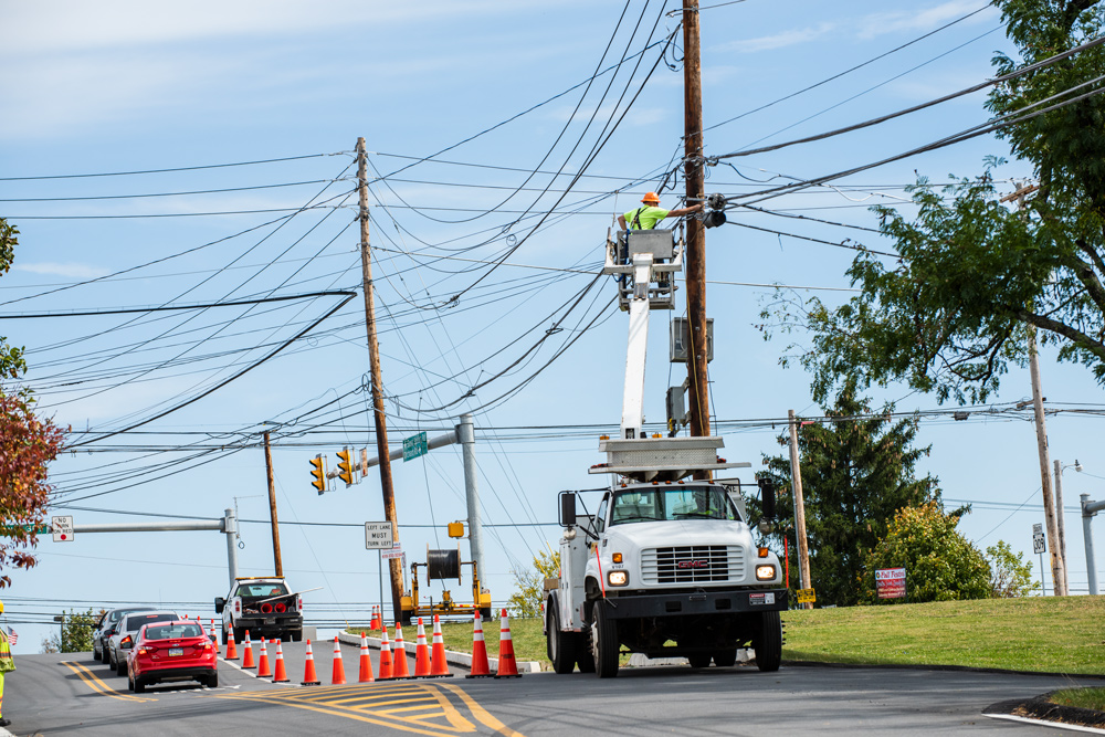
Broadband expansion depends on one critical resource that most people never think about: utility poles. These wooden structures carry power lines, cable TV, telephone wires, and fiber optic cables. When a telecommunications provider wants to add new fiber to a pole, it must navigate a complex process governed by federal regulations.

The Federal Communications Commission (FCC) sets the rules for pole attachments under Section 224 of the Communications Act. These rules determine how quickly broadband providers can access utility poles and how much they pay for that access. For contractors, engineers, and project managers working in telecom infrastructure, understanding these regulations is essential to keeping projects on schedule and within budget.

Recent updates to FCC pole attachment rules took effect on May 7, 2026, bringing significant changes to timelines and processes. These changes directly impact how One-Touch Make-Ready works in practice and create new opportunities for faster broadband deployment.

What Are FCC Pole Attachment Rules?

FCC pole attachment rules establish the framework for how telecommunications companies access utility poles owned by electric utilities and other pole owners. The rules cover everything from application procedures to pricing formulas to dispute resolution.

Under Section 224 of the Communications Act, the FCC has authority to regulate pole attachments to ensure that broadband providers have fair and reasonable access to utility infrastructure. This matters because approximately 70% of broadband networks in the United States rely on aerial construction using existing utility poles.

The core principle behind these regulations is simple: pole owners cannot unreasonably deny access or charge excessive fees. However, the practical application involves detailed timelines, notification requirements, and technical standards that govern every step of the attachment process.

Key Timeline Requirements Under Current Rules

The FCC's Fifth Report and Order, adopted in July 2025, established specific deadlines for each phase of the pole attachment process:

  • Application review: Utilities have 10 business days to determine if an application is complete
  • Survey completion: 45 days for standard orders; 90 days for large orders (over 300 poles)
  • Make-ready estimates: 14 days after survey completion for standard orders; 29 days for large orders
  • Make-ready work: 30 days in the communications space; 90 days in the power space for standard orders
  • Large order make-ready: 120 days in communications space; 180 days in power space

Federal rules now impose firmer timelines on the pole attachment process. The FCC's July 2025 order established a timeline for large pole attachment requests, accelerated contractor approval, and adopted measures to foster collaboration between utilities and attachers. Whether those changes will meaningfully speed deployment is not yet established. 

The Congressional Research Service notes that some states have reported timelines running up to five years in total for pole survey results and make-ready completion, and concludes that the effect of pole attachment issues on federally funded build-out deadlines remains to be seen. Regulatory fragmentation compounds the difficulty, with 23 states and the District of Columbia administering their own pole attachment rules rather than deferring to the FCC.

The Make-Ready Challenge

Make-ready work refers to the modifications needed on a utility pole before a new attachment can be installed. This might include moving existing cables, replacing hardware, or even replacing the entire pole if it cannot support additional load.

The traditional make-ready process creates a major bottleneck in broadband deployment. Here is why: each existing attacher on a pole must move its own equipment before the new attacher can install fiber. If a pole has cables from an electric utility, a telephone company, and a cable TV provider, each entity must schedule and complete its own work in sequence.

This sequential approach leads to significant delays. Industry data shows that make-ready timelines can stretch from 135 to 225 days before construction crews can install a single strand of fiber. The costs add up quickly too. Simple rearrangements typically cost $380 to $900 per pole, while complex work involving multiple parties can reach $2,100 per pole or more. Pole replacements can cost $3,400 to $6,500 per pole.

For a project involving hundreds or thousands of poles, these delays and costs can derail deployment schedules and strain budgets.

How One-Touch Make-Ready Changes the Game

One-Touch Make-Ready (OTMR) offers a solution to the sequential make-ready problem. Under OTMR, a single qualified contractor can perform all necessary rearrangement work in one coordinated visit, rather than waiting for each existing attacher to complete its portion separately.

The FCC adopted OTMR rules in 2018 for "simple make-ready" work in the communications space. Simple make-ready includes routine tasks like moving cables or adjusting attachment heights that do not require specialized skills or create safety concerns.

How OTMR Works in Practice

  1. Application submission: The broadband provider applies to attach to the pole
  2. Eligibility determination: The pole owner reviews the request and determines if OTMR applies
  3. Advance notice: The new attacher provides notice to the pole owner and existing attachers
  4. Single-crew execution: A qualified contractor performs all rearrangements in one mobilization
  5. New attachment installation: The fiber or communications equipment is installed

OTMR can compress make-ready timelines by 30 to 60 days on eligible projects. This acceleration is critical for meeting deployment deadlines, especially for projects funded through programs like the Broadband Equity, Access, and Deployment (BEAD) Program.

The 2026 FCC rule updates expanded self-help and OTMR rights for broadband builders. Utilities must now notify attachers within 15 days if they cannot meet survey or make-ready deadlines. This early warning allows attachers to invoke self-help remedies, including using their own qualified contractors to complete the work.

Connecting Pole Attachment Rules to OTMR Success

Understanding how FCC pole attachment rules relate to OTMR is essential for maximizing deployment efficiency. The regulations work together in several important ways.

Contractor Approval Timelines

The 2026 rules require utilities to respond within 30 days to requests from broadband providers seeking approval for new contractors to perform survey, estimate, and make-ready work. Previously, contractor approval could take months, creating a hidden bottleneck before OTMR could even begin.

Large Order Provisions

For large attachment requests (over 300 poles), the FCC created new advance notice and coordination requirements. Attachers must provide 15 days advance notice for mid-size orders (300 to 3,000 poles) and 30 days for very large orders (over 3,000 poles). These provisions help utilities plan resources while maintaining predictable timelines.

Restrictions on Utility Delays

The FCC prohibited utility-imposed limits that effectively cap how many pole attachments an attacher may seek in a given period. This prevents utilities from artificially slowing large-scale deployments by limiting application volume.

BEAD Program Compliance

Cooperatives and municipal utilities participating in the BEAD Program as subgrantees must now comply with FCC pole attachment rules as a condition of accepting funding. This extends federal protections to attachers working with entities that were previously exempt from Section 224 requirements.

Practical Implications for Telecom Infrastructure Projects

For organizations involved in broadband deployment, these regulatory changes create both opportunities and responsibilities.

Planning and Engineering

  • Accurate make-ready assessments are more important than ever. With tighter timelines, there is less room for surprises during construction. Comprehensive pole loading analysis and field surveys help identify potential issues before they cause delays.

Contractor Qualifications

  • OTMR eligibility depends on using qualified contractors approved by the pole owner. Organizations should maintain relationships with approved contractors and understand the approval process for new contractors in each utility territory.

Documentation and Compliance

  • The new rules include specific notification requirements and deadlines. Missing a deadline can forfeit self-help rights or trigger disputes. Robust project management systems help track applications, notices, and responses across large deployments.

Cost Management

  • Understanding make-ready cost allocation is critical for accurate budgeting. The FCC has clarified that new attachers cannot be forced to pay for pre-existing safety violations on poles. This ruling, issued in early 2026, protects attachers from bearing costs that should fall on pole owners.

Looking Ahead

The FCC continues to consider additional pole attachment reforms. A Fourth Further Notice of Proposed Rulemaking, released alongside the 2025 order, seeks comment on expanding OTMR to complex work and other streamlining measures. 

While no timeline exists for final action, the direction is clear: regulators want to remove barriers to broadband deployment. For telecom infrastructure professionals, staying current on these regulations is not optional. The rules directly impact project timelines, costs, and feasibility. Organizations that understand and leverage the regulatory framework will have a competitive advantage in winning and executing broadband projects.

Navigating FCC pole attachment rules and OTMR requirements takes specialized knowledge and experience. From OSP engineering and make-ready assessments to aerial construction and fiber splicing, having the right partner makes the difference between a project that stays on schedule and one that stalls in regulatory limbo.

Celerity Integrated Services brings decades of experience in telecommunications infrastructure, serving carriers, utilities, and organizations across the full project lifecycle. Whether you need engineering support for pole applications, One-Touch Make-Ready construction services, or ongoing maintenance, Celerity has the expertise to keep your project moving.

Ready to discuss your next broadband deployment? Contact Celerity to learn how our team can help you navigate pole attachment requirements and accelerate your timeline.

—Frequently Asked Questions

What are FCC pole attachment rules?

  • FCC pole attachment rules are federal regulations under Section 224 of the Communications Act that govern how telecommunications companies access utility poles. These rules establish timelines for application review, surveys, make-ready work, and pricing. They ensure broadband providers have fair and reasonable access to pole infrastructure for deploying fiber and other communications networks.

What is One-Touch Make-Ready?

  • One-Touch Make-Ready (OTMR) is a pole attachment process that allows a single qualified contractor to perform all necessary rearrangement work on a utility pole in one visit. Instead of waiting for each existing attacher to move its equipment separately, OTMR consolidates the work, reducing make-ready timelines by 30 to 60 days on eligible projects.

How long does the pole attachment process take under current FCC rules?

  • Under the FCC's 2026 rules, standard pole attachment requests follow a 148-day framework from application to construction authorization. This includes 10 business days for application review, 45 days for surveys, 14 days for estimates, and 30 to 90 days for make-ready work depending on the space involved. Large orders have extended timelines of up to 90 days for surveys and 120 to 180 days for make-ready.

What services does Celerity provide for pole attachment projects?

  • Celerity Integrated Services provides comprehensive telecommunications infrastructure services including OSP engineering, make-ready assessments, pole application processing, aerial and underground construction, fiber splicing and testing, and One-Touch Make-Ready construction. The company serves telecommunications carriers, electric utilities, and organizations throughout all project phases from planning through maintenance.

How do the 2026 FCC pole attachment rules affect BEAD-funded projects?

  • The 2026 rules extend FCC pole attachment protections to cooperatives and municipal utilities participating in the BEAD Program as subgrantees. This means BEAD-funded projects benefit from federal timeline requirements and self-help remedies, even when working with pole owners that were previously exempt from Section 224 regulations.

What is make-ready work and why does it cause delays?

  • Make-ready work includes any modifications needed on a utility pole before a new attachment can be installed, such as moving existing cables, replacing hardware, or replacing poles. Delays occur because traditional processes require each existing attacher to complete its work sequentially. Industry data shows make-ready can take 9 to 16 months, with some projects experiencing delays of up to five years.

August 26, 2026

What Does a Telecommunications Contractor Do? A Complete Guide for Network Owners

The fiber optic network connecting your business to the world did not appear by magic. Behind every reliable connection sits months of planning, miles of cable, and teams of skilled professionals who make it all work. These professionals are telecommunications contractors, and their role in building modern infrastructure has never been more critical.

With fiber broadband now reaching over 60% of U.S. households and 2025 setting an all-time record for network deployment, understanding what these contractors do helps organizations make smarter decisions about their connectivity investments.

Understanding the Role of a Telecommunications Contractor

A telecommunications contractor is a specialized company that designs, builds, installs, and maintains communication networks. Think of them as the architects and builders of the digital highway system. They handle the physical infrastructure that makes phone calls, internet access, and data transmission possible.

These contractors work across multiple environments. Some focus on outside plant (OSP) construction, which includes everything installed outdoors: underground cables, aerial lines on poles, and the equipment that connects them. Others specialize in wireless infrastructure, building the fiber backhaul that supports cell towers and 5G networks.

The scope of work varies widely. A telecommunications contractor might spend one week installing fiber optic cables beneath city streets using horizontal directional drilling. The next week, that same team could be splicing fiber strands in a rural area to bring broadband to underserved communities.

What separates professional contractors from general construction firms is their specialized expertise. Fiber optic work requires precision measured in microns. A single poorly executed splice can degrade network performance for thousands of users. This technical depth is why carriers, utilities, and enterprises rely on dedicated telecommunications contractors rather than general contractors.

Core Services Telecommunications Contractors Provide

Telecommunications contractors offer a range of interconnected services that span the entire network lifecycle. Understanding these services helps organizations identify what they need and evaluate potential partners effectively.

Engineering and Network Design

Before any cable goes into the ground, contractors perform detailed engineering work. This includes route surveys to identify the best paths for cable runs, feasibility studies to assess construction challenges, and network characterization planning to ensure the finished system meets performance requirements.

Good engineering prevents expensive problems later. A thorough survey identifies underground utilities, soil conditions, and permit requirements before construction begins. Skipping this step often leads to costly delays and change orders.

Aerial and Underground Construction

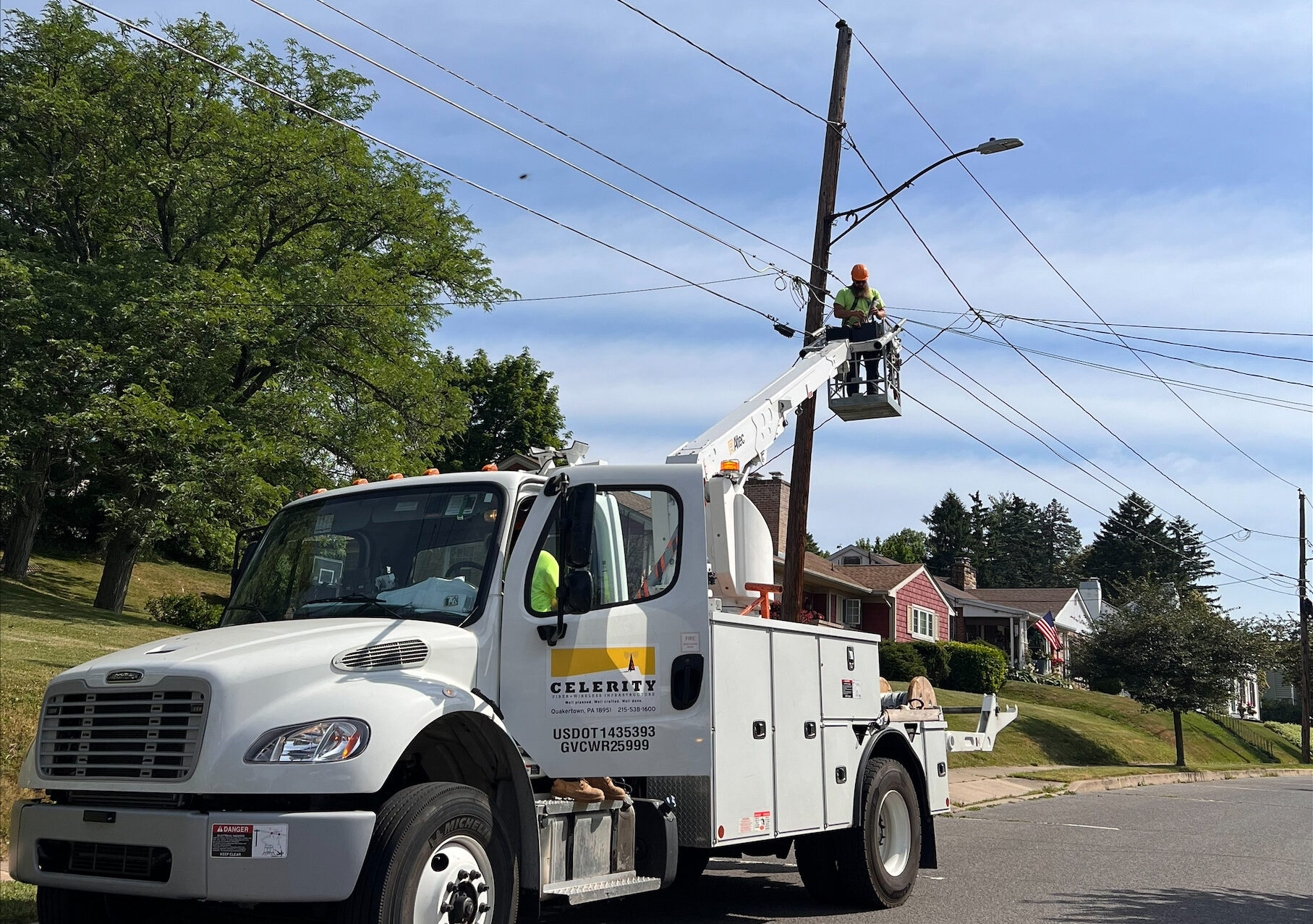
The physical construction phase involves two primary methods: aerial installation on existing poles and underground placement through trenching or directional drilling.

Aerial construction typically costs less and moves faster when pole infrastructure already exists. Underground construction offers better protection from weather and physical damage but requires more extensive civil works.

Modern contractors use horizontal directional drilling (HDD) to install cables beneath roads, rivers, and other obstacles without surface disruption. This technique minimizes traffic impacts and reduces restoration costs compared to traditional open-cut trenching.

Fiber Optic Splicing and Testing

Once cables are in place, technicians splice individual fiber strands together using fusion splicing equipment. This process requires clean room conditions and specialized training. A quality splice introduces minimal signal loss and lasts for decades.

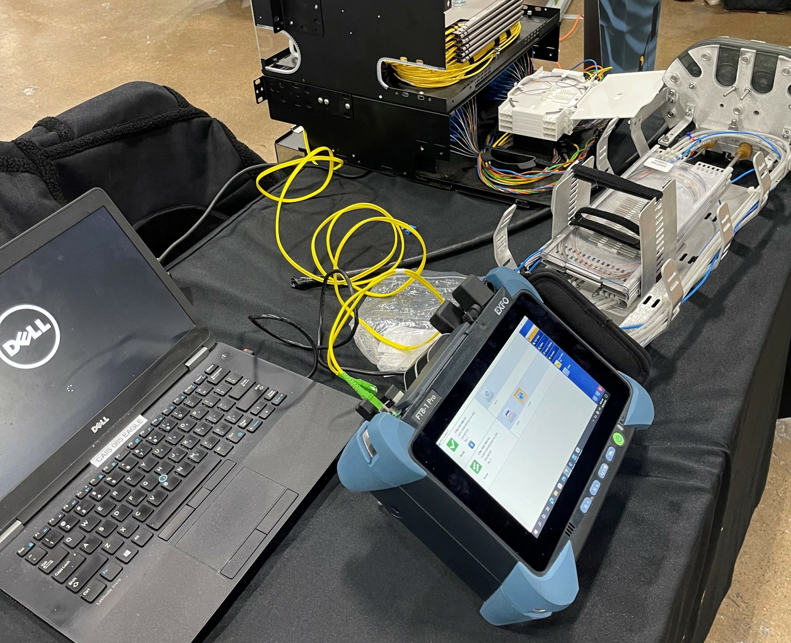
Testing follows splicing to verify network performance. Contractors use optical time-domain reflectometers (OTDRs) to measure cable length, locate faults, and confirm splice quality. Power meter and light source testing validates end-to-end signal transmission.

Advanced characterization testing goes further, measuring optical return loss, chromatic dispersion, and polarization mode dispersion. These tests matter most for high-capacity networks where even small imperfections affect performance.

Maintenance and Emergency Restoration

Networks require ongoing care. Preventive maintenance programs catch problems before they cause outages. Regular fiber audits reconcile documentation with actual field conditions, ensuring records stay accurate as networks evolve.

When damage occurs, whether from construction accidents, severe weather, or equipment failure, emergency restoration services get networks back online quickly. Contractors with 24/7 response capabilities minimize downtime and its associated costs.

The Telecom Infrastructure Project Lifecycle

Successful network projects follow a predictable sequence. Understanding this lifecycle helps organizations plan timelines, allocate budgets, and set realistic expectations.

Phase 1: Planning and Engineering

The project begins with detailed planning. Engineers survey proposed routes, identify obstacles, and design solutions. This phase produces construction drawings, material lists, and permit applications. Rushing through planning almost always creates problems during construction.

Phase 2: Permitting and Coordination

Telecommunications construction requires permits from multiple authorities: municipalities, state agencies, railroads, and private property owners. Experienced contractors know local requirements and maintain relationships that smooth the approval process. Permit delays are among the most common causes of project schedule slippage.

Phase 3: Civil Works and Construction

With permits in hand, construction crews mobilize. Civil works include trenching, conduit installation, manhole construction, and pole attachment. This phase is the most visible and often the most weather-dependent.

Phase 4: Cable Installation and Splicing

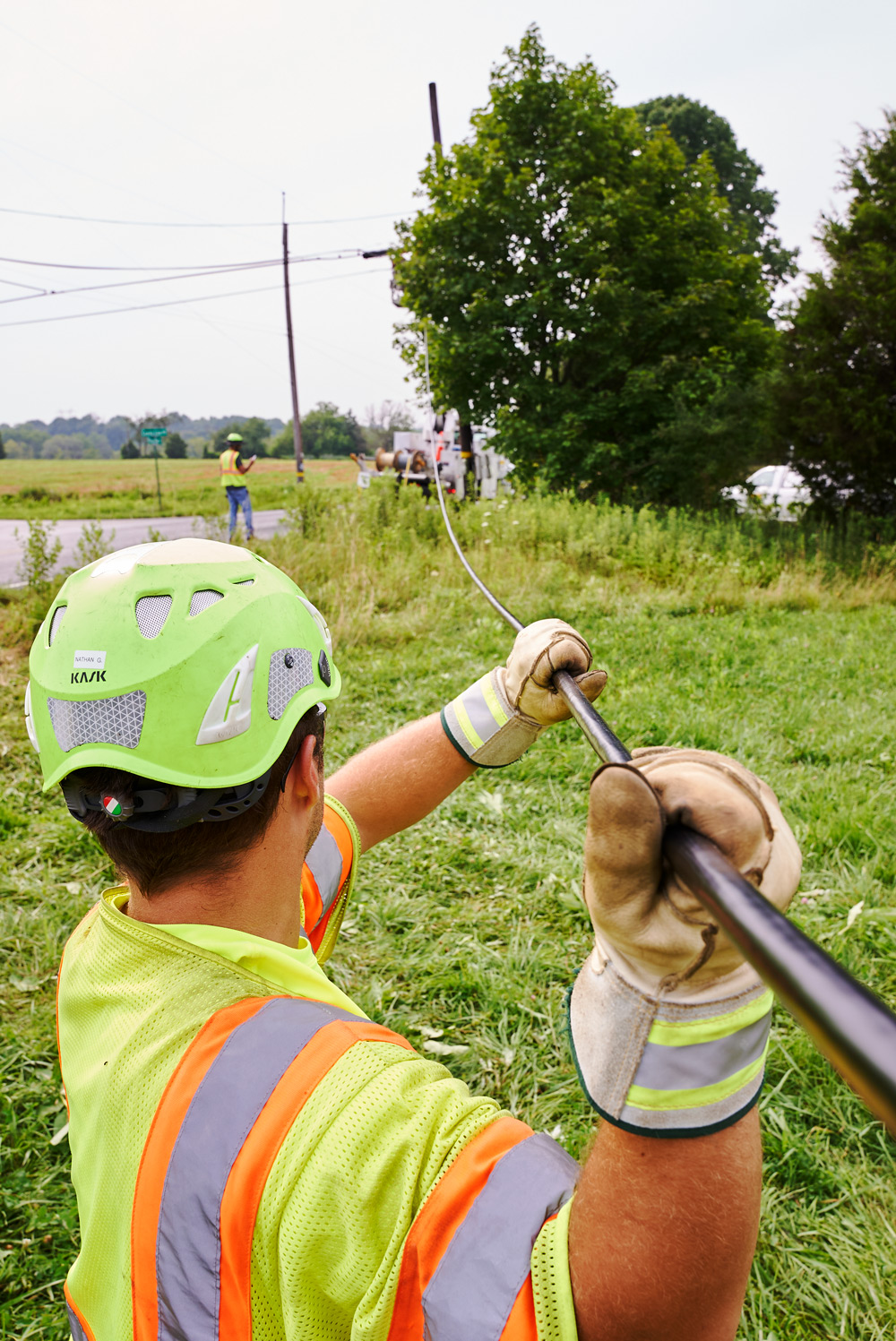
Crews pull or blow fiber optic cables through conduits and splice them at designated points. Documentation during this phase is critical. Accurate splice records and cable routing information support future maintenance and troubleshooting.

Phase 5: Testing and Commissioning

Comprehensive testing validates that the installed network meets specifications. Test results become part of the permanent project record. Any deficiencies identified during testing get corrected before handover.

Phase 6: Documentation and Handover

The contractor delivers as-built drawings, test results, and maintenance documentation to the network owner. Quality documentation supports efficient operations for years to come.

Phase 7: Operations and Maintenance

Many contractors offer ongoing maintenance services after construction. These arrangements range from on-call emergency response to comprehensive managed services that handle all routine maintenance.

How to Choose the Right Telecommunications Contractor

Selecting the right contractor significantly impacts project success. Several factors deserve careful evaluation.

Safety Record and Certifications

Telecommunications construction involves real hazards: working at heights, operating heavy equipment, and handling electrical systems. Request safety statistics and verify certifications. Contractors with strong safety cultures protect their workers and reduce project risk.

Industry certifications from organizations like the Fiber Optic Association indicate that technicians have demonstrated competency through standardized testing.

Equipment and Workforce

Contractors who own their equipment and employ their technicians directly typically deliver more consistent quality than those relying heavily on subcontractors. Ask about crew composition and equipment ownership.

Documentation Practices

Poor documentation creates long-term headaches. Evaluate sample deliverables from previous projects. Quality contractors produce clear, accurate records that support efficient network operations.

Financial Stability

Large infrastructure projects span months or years. Verify that potential contractors have the financial strength to complete your project without disruption.

Why Fiber and Wireless Infrastructure Matters Now

The telecommunications industry is experiencing unprecedented growth. The Fiber Broadband Association reports that 11.8 million U.S. homes gained fiber access in 2025 alone, setting an all-time deployment record. Total fiber passings now approach 100 million.

Federal programs like the $42.45 billion Broadband Equity, Access and Deployment (BEAD) initiative are accelerating construction in underserved areas. At least 18 states have BEAD-funded fiber projects currently under construction.

This growth creates both opportunity and challenge. Organizations planning network projects face a competitive market for contractor services. Starting the selection process early and building relationships with qualified contractors improves outcomes.

The trend toward fiber dominance shows no signs of slowing. Industry projections indicate fiber will overtake cable as the dominant U.S. broadband delivery platform by 2028. Organizations investing in fiber infrastructure today are positioning themselves for decades of reliable connectivity.

Choosing the right telecommunications contractor gives network owners access to the engineering expertise, skilled workforce, specialized equipment, and documentation practices needed to build reliable infrastructure and protect it throughout its lifecycle. Contact Celerity Integrated Services to discuss how its end-to-end engineering, construction, fiber splicing, testing, maintenance, and emergency restoration capabilities can support your next telecommunications infrastructure project.

June 17, 2026

How to Connect Multi-Campus University Systems with Smart OSP Engineering

Universities don't run on good intentions. They run on bandwidth. Every lecture hall streaming video. Every research lab transferring massive datasets. Every residence hall full of students who expect instant connectivity. When a campus spans multiple locations (sometimes miles apart) the fiber network connecting them isn't just infrastructure. It's the backbone of its operations.

Connecting multi-campus systems is nothing like wiring a single building. The challenges multiply. The stakes get higher. And the margin for error shrinks to almost nothing. These challenges are what many facilities teams discover too late in the planning process.

So how does a university get it right? It starts with understanding what makes university OSP (Outside Plant) engineering fundamentally different, and what questions to ask before actual work begins. The fiber optic market is growing at a compound annual growth rate of 16.64% through 2034, according to industry analysts. Universities are racing to keep pace with bandwidth demands that seem to double every few years. But rushing a multi-campus buildout without proper OSP engineering creates problems that last decades.

Why Multi-Campus Fiber Networks Are Different

A single-campus network has one set of stakeholders, one terrain profile, and one construction timeline to manage. Multi-campus systems multiply every variable. They deal with different soil conditions at each location. Different building ages and entry point challenges. Different departmental priorities competing for attention. And often, different local permitting requirements depending on where each campus sits.

In our work with higher education clients, we've seen institutions inherit networks designed 15 years ago that can't support today's computing needs. The original engineers didn't plan for growth. They didn't build in redundancy. And now, retrofitting costs three times what doing it with all these variables taken into account would have cost originally.

The 5 Biggest OSP Challenges Universities Face

1. Terrain That Doesn't Cooperate

Every campus has obstacles such as historic quads, mature tree canopies, and underground utilities from decades ago that don't show up on satellite imagery. Rocky terrain is particularly challenging. One project we supported involved a campus built on Pennsylvania bedrock. Standard trenching wasn't an option. The engineering team had to design around geological surveys, using directional boring and strategic aerial segments to complete the backbone.

2. Academic Calendar Constraints

Campus construction schedules need to align with the academic calendar. Contractors cannot disrupt the main walkways during move-in weekend or operate heavy equipment near the library, for example, during finals. On university campuses, workable construction windows are often measured in weeks rather than months.

Effective OSP planning integrates the academic calendar into the project timeline from the start. Teams phase work during summer breaks, coordinate around major campus events, and prepare contingency plans when weather delays threaten to extend work into the fall semester.

3. Stakeholder Complexity

A corporate campus has one decision-maker. A university has dozens. IT wants maximum bandwidth. Facilities department wants minimal disruption. The provost wants the project done before the capital campaign launch. The grounds department wants to protect the historic elm trees. And everyone has veto power over something.

Successful multi-campus projects require a feasibility study that gets all stakeholders aligned before design begins. Otherwise, the redesign might involve multiple rounds.

4. Future-Proofing Uncertainty

How much bandwidth will a campus need in 2035? Nobody knows for certain. But the fiber installed today needs to handle whatever comes next. A 288-count fiber backbone costs marginally more than 144-count during installation. But adding capacity later means digging up the same routes again.

5. Budget Realities

An OSP infrastructure typically represents 60-70% of total network capital expenditure. Underground installation runs $5,000 to $20,000 per mile depending on conditions. The institutions that stay on budget are the ones that invest in thorough engineering upfront. Every dollar spent on route optimization and constructability analysis saves dollars during construction.

Planning A Multi-Campus Fiber Architecture

The most resilient university networks follow a three-tier hierarchical model:

  • Core Layer: The central data center or network operations center that serves as the hub for all campus connections.
  • Distribution Layer: Major buildings on each campus that aggregate traffic from surrounding structures.
  • Access Layer: Individual buildings, labs, and facilities that connect to their nearest distribution point.

This architecture creates natural redundancy. If one distribution node fails, traffic can reroute through alternate paths. For multi-campus systems, it also allows each location to operate semi-independently during maintenance windows.

The key decision is where to place the distribution nodes. They need to be:

  • Geographically central to the buildings they serve
  • Accessible for maintenance without disrupting campus operations
  • Protected from environmental risks (flooding, construction zones)
  • Connected to at least two independent pathways back to the core

Underground vs. Aerial: Making the Right Call

Every multi-campus project faces this question: is the fiber buried, or is it strung overhead?

Underground Advantages

Underground infrastructure provides several key advantages. It remains protected from weather, vehicle damage, and vandalism. It typically delivers a longer lifespan while requiring less maintenance. Once installed, it stays visually unobtrusive and preserves the surrounding aesthetic. In many historic districts, underground placement is also required.

Underground Challenges

Underground construction also presents several challenges. It often carries higher installation costs and requires a longer project timeline. Excavation can disrupt campus operations and daily activities during construction. Installation can also become more complex in rocky terrain or in utility corridors that are already congested.

Aerial Advantages

Aerial infrastructure offers several advantages. It can be installed more quickly, typically requires lower upfront costs, and allows easier access for repairs and maintenance. It also performs well in areas where existing pole infrastructure is already in place.

Aerial Challenges

Aerial deployment also comes with challenges. Because it remains exposed, it is more vulnerable to weather-related damage. It can affect campus aesthetics, often requires pole attachment agreements, and may have a shorter lifespan in harsh climates.

Most university projects use a hybrid approach. Underground for high-visibility areas and critical backbone routes. Aerial for back-of-campus connections and temporary construction phases. The right mix depends on specific conditions. A thorough engineering assessment maps every route option before recommending the optimal combination.

Real-World Success: Lessons from Complex Buildouts

One project that illustrates these principles involved connecting three separate campus locations for a major Pennsylvania university. The scope included:

  • 288-count fiber backbone across all three sites
  • Underground installation through rocky terrain
  • Coordination with ongoing campus construction
  • Redundant pathways for failover protection

The engineering team conducted geological surveys before finalizing routes. They identified areas where bedrock made trenching impractical and designed directional boring solutions. They scheduled major excavation during summer break and used fiber splicing techniques that minimized splice points along the route.

The project was completed on budget and the difference was investing time in planning before construction began.

Getting Started: Next Steps

If you're considering a multi-campus fiber buildout, here's where to begin:

  1. Audit your existing infrastructure. What fiber is already in the ground? What condition is it in? What capacity does it have?
  2. Map your bandwidth requirements. Not just today's needs—project forward 10-15 years. Include research computing, IoT expansion, and technologies that don't exist yet.
  3. Engage stakeholders early. Get IT, facilities, administration, and academic leadership aligned on priorities before you start designing.
  4. Commission a feasibility study. A thorough engineering assessment identifies obstacles, estimates costs, and creates realistic timelines.
  5. Choose partners with university experience. Multi-campus buildouts have unique challenges. Work with teams who've solved them before.

Getting it right matters. And it starts with asking the right questions. Celerity has supported complex fiber infrastructure projects for more than 20 years, including multi-campus university systems across the Northeast. Contact our engineering team to discuss your project.

June 10, 2026

Why Bandwidth-Intensive Research Universities Cannot Afford to Lease Fiber Infrastructure

Research universities are entering an era where bandwidth has become as essential as power, water, and laboratory space. Advanced AI workloads, genomics research, high-performance computing, immersive learning environments, and cloud-based collaboration now move enormous volumes of data across campus every hour. Infrastructure decisions that once seemed routine have become strategic.

For many institutions, leased connectivity no longer keeps pace with the speed of innovation. Capacity limits, contract constraints, and delayed upgrades can slow research momentum and create unnecessary costs. Universities that control their own fiber networks often gain the flexibility to scale faster, protect critical data, and support future growth on their own timeline.

The question is no longer whether campuses need more bandwidth. The real question is who controls it.

The Bandwidth Crisis Facing Research Universities

Research universities aren't just schools with bigger libraries. They're data factories. Modern academic research generates staggering amounts of information. High-performance computing clusters process climate simulations. Medical imaging systems transfer terabytes of scans daily. AI and machine learning labs train models that demand constant data flow between GPUs and storage systems.

Recent infrastructure assessments show that university high-performance computing environments now require 100 to 400 Gbps interconnects for node-to-node communication. As research workloads become more data intensive, bandwidth expectations continue to rise across the campus ecosystem.

Campus backbone networks increasingly need 100 to 400 Gbps capacity to support research traffic, enterprise systems, and growing digital demand. Research data centers often require dedicated 40 to 100 Gbps connections to move large datasets efficiently between facilities. High-performance computing clusters rely on InfiniBand networks operating at 100 Gb/s line rates to reduce latency and maximize performance. AI training environments push requirements even further, with GPU clusters demanding massive memory bandwidth measured in terabytes per second.

When an institution’s competitive edge depends on how quickly it can process, move, and analyze data, network infrastructure is no longer just an IT function. It becomes a strategic asset.

Leased Fiber: The Hidden Long-Term Costs

Leasing fiber seems attractive at first glance. Low upfront costs. Someone else handles maintenance. Quick deployment.

But here's what the sales pitch doesn't mention. Leased fiber means monthly payments that never stop. A 10 Gbps dedicated connection might cost $5,000-$15,000 per month depending on location and provider. Over a decade, that's $600,000 to $1.8 million for a single connection. Research universities typically need dozens of high-capacity links across campus. 

Scalability Bottlenecks

Need more bandwidth? With leased fiber, you're negotiating new contracts. Waiting for provider approval. Paying premium upgrade fees. Upgrading bandwidth often requires negotiating a new contract and paying higher recurring fees, which can be slow and expensive. For research institutions racing against grant deadlines and competing for federal funding, "slow" isn't acceptable.

Limited Control

Leased fiber means someone else controls your network's destiny. Maintenance schedules. Technology choices. Security protocols. When your institution's most sensitive research data flows through infrastructure you don't control, that's a risk worth considering.

Owned Fiber Infrastructure: The Strategic Advantage

Fiber cables aren't like computers that become obsolete in five years. Properly installed fiber infrastructure lasts 30 to 50 years with minimal maintenance, according to Penn State Extension research.  This longevity transforms the financial equation. While leased fiber costs accumulate indefinitely, owned fiber becomes a depreciating asset that continues delivering value for decades.

The greatest advantage of owned fiber is that long-term capacity depends largely on the endpoint electronics rather than the cable itself. The same physical fiber carrying 10 Gbps today can often support 400 Gbps tomorrow through upgrades to transceivers, lasers, and switching equipment at each end of the connection. The institution can expand performance without new trenching, contract renegotiations, or lengthy carrier approval cycles.

For research universities where bandwidth demand grows rapidly through AI workloads, advanced computing, and data-intensive collaboration, that level of flexibility delivers significant strategic value.

Total Cost of Ownership Wins

When a university owns its fiber infrastructure, it controls the critical decisions that shape network performance and security. The institution can set encryption standards, manage access permissions, determine maintenance schedules, and implement technology upgrades on its own timeline.

That level of control matters deeply for universities handling sensitive research and regulated information, including defense-related projects, medical data, and proprietary discoveries. In those environments, network oversight is not a convenience. It is a requirement.

Lehigh University: A Case Study in Strategic Infrastructure

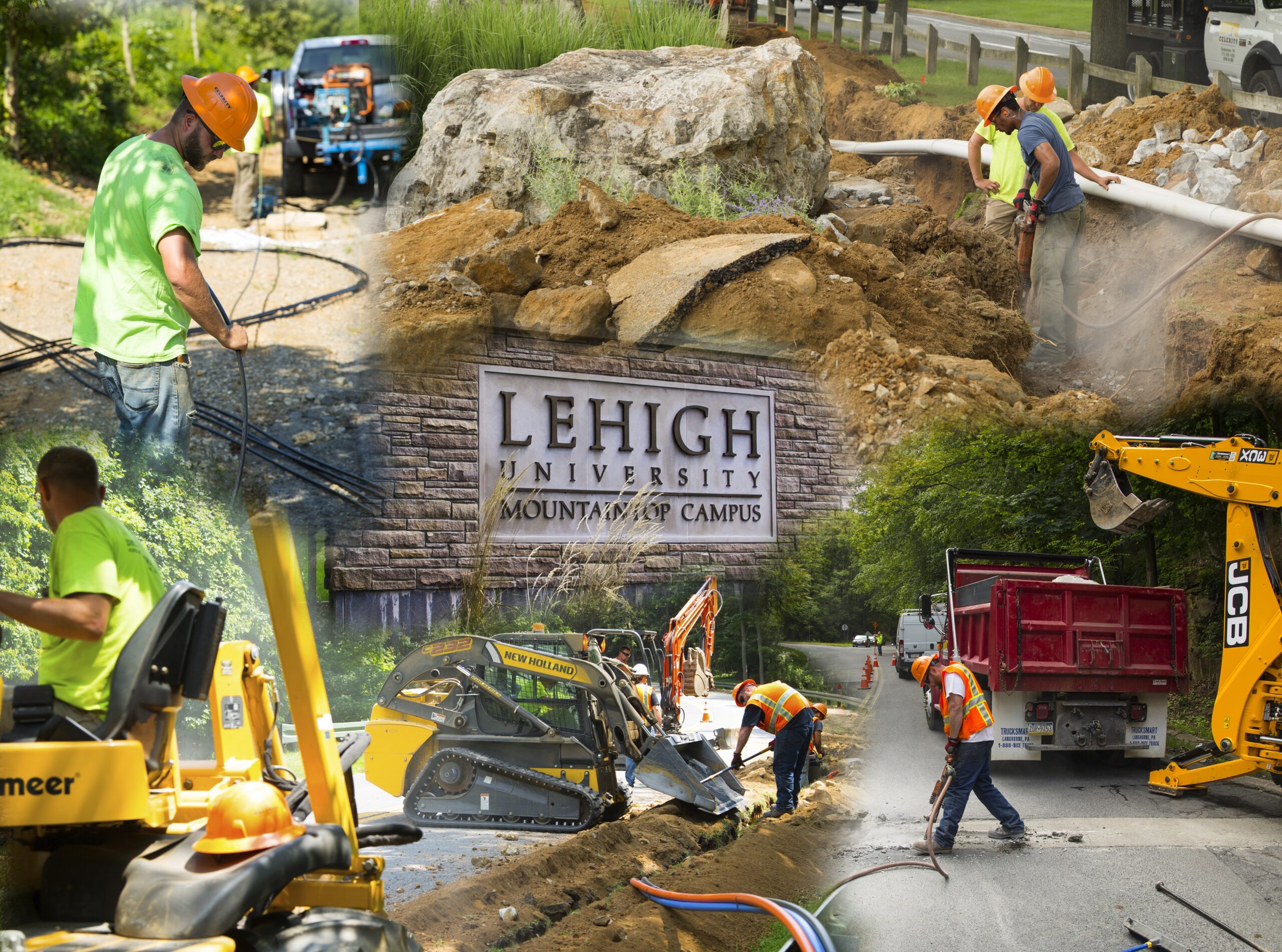
When Lehigh University needed to connect its Goodman, Asa Packer, and Mountain Top campuses, leadership faced a strategic infrastructure decision. The university could continue relying on a patchwork of leased connections and vulnerable aerial cable systems, or it could invest in owned infrastructure designed for long-term growth. The university chose ownership.

Through the Celerity Lehigh project, the institution deployed high-capacity 288-count underground fiber optic cable between campuses. The investment addressed several pressing issues, including capacity limitations affecting the Data X research initiative, recurring exposure to falling trees, rodent damage, and traffic-related disruptions, as well as ongoing maintenance demands tied to aging aerial infrastructure.

The new network significantly expanded available capacity while creating true redundancy to help protect mission-critical research data. By moving the system underground, the university also reduced many of the environmental risks that had impacted the previous network.

Most importantly, Lehigh now controls its long-term network roadmap. Future bandwidth upgrades can be achieved through electronics improvements rather than new construction projects or carrier contract negotiations.

Making the Right Choice 

Successful fiber ownership begins with disciplined planning. Universities and other large institutions should first evaluate current bandwidth demand and forecast future needs across every campus location, facility, and strategic initiative. A clear understanding of long-term growth helps ensure the network is built for tomorrow rather than only for today.

The next step involves feasibility studies that examine routes, terrain conditions, utility conflicts, and existing infrastructure. From there, experienced outside plant engineering partners can develop detailed network designs that address capacity, resiliency, and expansion opportunities. Strong planning should also account for construction realities such as permitting requirements, right-of-way access, traffic flow, and minimizing disruption to campus operations.

Just as important, institutions should document every aspect of the project, including routes, assets, splice points, and design decisions, so future maintenance and upgrades can be managed efficiently.

The upfront investment in planning creates value throughout construction and continues paying dividends for decades through lower risk, smoother operations, and easier expansion.

The Bottom Line

Research universities compete on their ability to attract talent, win grants, and produce breakthrough discoveries. All of these depend on infrastructure that can handle tomorrow's data demands. Leased fiber locks institutions into recurring costs and limited scalability. Owned fiber infrastructure delivers control, flexibility, and long-term savings.

In an industry where only 8.5% of construction projects finish on time and on budget, choosing the right partner matters as much as choosing the right strategy. Universities need contractors who understand the unique demands of campus environments such as the safety requirements, the scheduling constraints, and the documentation needs.

The institutions building owned fiber infrastructure today are positioning themselves for decades of competitive advantage. Those still leasing are paying more for less and falling further behind with every monthly invoice.

Contact Celerity to discuss feasibility studies, engineering, and construction for your campus network.


June 3, 2026

How to Build a Business Case for Campus Fiber Ownership: A Guide for University IT and Finance Leaders

A campus network supports far more than connectivity. It powers research, online learning, administrative systems, student services, and the daily digital experience across the institution. Yet many universities still lease bandwidth from carriers, paying recurring fees while outside providers control capacity, upgrade timelines, and key network decisions.

Fiber ownership offers a different path. It starts with a question IT leaders and finance teams should evaluate together: what would change if the institution owned the fiber instead?
Building that business case requires both technical and financial discipline. When universities align network requirements with long-term capital planning, they can shift from unpredictable operating expenses to a depreciable infrastructure asset designed to serve the campus for decades.


This guide walks through that framework step by step.

Why Campus Fiber Ownership Matters 

Higher education faces a perfect storm of pressures. Enrollment competition is fierce. According to the National Student Clearinghouse Research Center, fall 2025 enrollment reached 19.4 million students, but private nonprofit four-year institutions saw a 1.6% decline. Students have options. And increasingly, they're choosing institutions that deliver seamless digital experiences.

Meanwhile, bandwidth demands are exploding. AI research computing, hybrid learning platforms, IoT sensors across facilities, and hundreds of thousands of connected devices require infrastructure that can scale without carrier negotiations.

The institutions that own their fiber networks control their destiny. Those that lease? They're at the mercy of service agreements, capacity limits, and annual price increases.

Ownership vs. Leasing: Understanding the Real Trade-Offs

Let's be direct about what each model actually means.

  • Leasing bandwidth 
    • Operates primarily on operational expenditure (OpEx). You pay monthly fees for capacity. When you need more, you pay more. There's no upfront capital outlay, which appeals to institutions with constrained budgets or uncertain future demands. But here's the catch: total cost of ownership rises linearly as your network grows. Every bandwidth upgrade means another line item on next year's budget.
  • Owning dark fiber 
    • Requires substantial upfront capital investment. You're purchasing infrastructure, not renting it. But ownership delivers lower total cost of ownership at scale—particularly for institutions expecting network demands of 3x100Gbps or more. You choose your own wavelength technologies, capacity levels, and upgrade paths. No carrier dependencies. No surprise fees when you need to scale.

There's also a security dimension. Owned fiber enables private, high-security networks where traffic stays off public internet and carrier networks entirely. For research institutions handling sensitive data, this isn't a nice-to-have. It's essential. Some institutions explore Managed Optical Fiber Networks (MOFN), which blend ownership benefits with managed services. This approach works well when acquiring dark fiber poses challenges or when your team prefers delegating network operations to a provider while retaining infrastructure control.

Building A Business Case: The 5-Pillar Framework

A compelling business case speaks two languages: technical necessity and financial return. Here's the framework that works.

Pillar 1: Current State Audit

The first step is understanding what the institution is actually spending today. Finance and IT teams should review at least three years of network service invoices and document every carrier contract, bandwidth tier, recurring fee, and overage charge. They should also map the current network environment, identifying what infrastructure the university owns, what it leases, and what assets are approaching end of life.

This type of audit often uncovers meaningful opportunities. Institutions frequently find hidden costs, overlapping services, underused capacity, or legacy agreements that no longer align with current needs. Just as importantly, the audit establishes a clear financial baseline for evaluating ROI and comparing ownership against continued leasing. A thorough fiber audit can identify infrastructure gaps and document existing assets with precision.

Pillar 2: Demand Forecasting

Institutions should project bandwidth needs across the next decade rather than planning only for current demand. That forecast should account for research computing initiatives, especially AI and machine learning workloads, enrollment growth or stabilization goals, expansion of hybrid and online learning, IoT deployments across campus facilities, and connectivity requirements between multiple campuses or remote sites.

Leadership should approach these estimates with ambition rather than caution. Fiber infrastructure often remains in service for 25 to 30 years or longer, so underbuilding can create expensive limitations later. 

Many universities continue to rely on fiber installed decades ago while upgrading the electronics layered on top of it to meet modern performance needs. The most effective strategy is to build for where the institution is headed, not where it stands today.

Pillar 3: Total Cost of Ownership Analysis

This is where the business case lives or dies. Model two scenarios across 10 years:

Scenario A (Leasing): Current carrier costs, projected annual increases (typically 3-5%), capacity upgrade fees, contract renewal terms.

Scenario B (Ownership): Capital investment for fiber installation, optical equipment, operations support, ongoing maintenance, and staff requirements.

For institutions with substantial bandwidth demands, fiber ownership often reaches breakeven within five to seven years. After that point, the network can generate meaningful long-term savings across the remaining life of the infrastructure, which often extends another 18 to 23 years or more.

A thorough financial model should also account for costs that are frequently overlooked in standard comparisons. These include staff time spent managing carrier relationships and contract renewals, downtime or productivity losses caused by capacity constraints, and the opportunity cost of delayed research initiatives or postponed technology programs. Including these factors creates a far more accurate view of total value.

Pillar 4: Risk Assessment and Redundancy

Fiber ownership isn't just about cost. It's about control and resilience.

When Lehigh University needed to connect three campuses with a robust, redundant fiber network, they faced real challenges: steep terrain, rocky soil, and construction that couldn't disrupt student life. The solution? A 288-count buried fiber build (not aerial), constructed during off-hours, completed within one year and on budget. That redundancy now protects research and academic data from environmental outages.

Document the risks of not owning your infrastructure: carrier outages, contract disputes, capacity constraints during critical periods, and dependency on third-party upgrade timelines.

Pillar 5: Stakeholder Presentation

CFOs and board members evaluate decisions through financial impact, risk, and long-term institutional value rather than technical specifications alone. That means network proposals should translate bandwidth needs into clear business language.

Ownership can shift unpredictable monthly operating expenses into a depreciable capital asset with long-term utility. A single investment may provide 25 to 30 years of service life, creating a stronger return profile over time. Modern infrastructure can also strengthen competitive positioning by supporting student recruitment, retention, digital learning expectations, and campus experience. 

For research institutions, greater capacity can enable grant-funded initiatives, advanced computing programs, and revenue-generating partnerships that depend on robust connectivity.

The most effective presentation often starts with a 10-year total cost of ownership comparison, then addresses risk reduction and operational resilience, and closes by showing how the investment supports broader strategic goals.

Total Cost of Ownership: What the Numbers Actually Show

Industry data shows that organizations crossing the 3x100Gbps threshold see distinct TCO advantages with ownership versus leasing. The math shifts because leasing costs scale linearly with demand, while ownership costs remain relatively fixed after initial investment.

Consider the Decorah, Iowa, municipal fiber model: a $13.7 million investment delivering gigabit symmetrical service with full local control. The ownership model avoided public-private partnership pitfalls and created long-term infrastructure value for the community.

Universities operate on similar logic. A campus fiber network isn't a multi-decade asset. When you factor in:

  • Elimination of recurring carrier fees
  • Unlimited capacity scaling without service charges
  • Equipment ownership (no lease-end surprises)
  • Reduced vendor dependency

The ownership model often delivers 40-60% lower TCO over a 20-year horizon compared to equivalent leased capacity.

Making the Case to Your Board: Practical Next Steps

Here's your action plan.

Step 1: Commission a feasibility study that maps your current infrastructure, projects future demands, and models ownership versus leasing scenarios.

Step 2: Engage OSP engineering expertise to design a network that meets your specific campus topology, whether that's aerial construction, underground builds, or a hybrid approach.

Step 3: Build your presentation around the 5-pillar framework. Lead with financials, support with technical necessity, close with strategic vision.

Step 4: Plan for ongoing maintenance from day one. A 25-year asset requires a 25-year maintenance strategy.

In our work with educational institutions, we've seen the difference between networks built for today and networks built for tomorrow. The institutions that invest in ownership with proper planning, quality construction, and meticulous documentation position themselves for decades of competitive advantage. Contact us to discuss your campus fiber ownership project.

April 13, 2026

Disaster Recovery in Action: How Celerity Restores Fiber Networks After Storm Damage

At 3:47 AM on a Tuesday morning, the emergency line rang at Celerity Integrated Services. A severe thunderstorm had torn through eastern Pennsylvania, and a regional internet service provider's fiber network was down. Completely down. No signal. No connectivity. For businesses relying on that network such as hospitals for transmitting patient records, financial institutions for processing transactions, emergency services for coordinating responses, the outage wasn't just an inconvenience. It was a crisis.

And with every passing minute, the cost was climbing. For such incidents, costs can reach more than $300,000 per hour in lost revenue and productivity, according to recent industry data from ITIC's 2024 downtime study. This is where fiber optic emergency restoration becomes more than a service. It becomes a lifeline.

The Call That Changes Everything

When disaster strikes a fiber network, the first 60 minutes determine everything. Will the provider scramble to find contractors? Will they waste precious time locating equipment? Or will they have a partner who's already prepared, already moving, already on the way?

Celerity's emergency response team was mobilized within 20 minutes of that early morning call. The crew knew the drill: grab the pre-staged emergency restoration kit, load the bucket truck with fusion splicers and OTDR testing equipment, and head to the site. No delays. No excuses.

The storm had knocked down three utility poles along a rural stretch of Route 309, taking the aerial fiber cable with them. But here's the challenge: the network spanned 12 miles. Where exactly was the damage?

This is where fiber network validation technology becomes critical. Celerity's technicians deployed an Optical Time Domain Reflectometer (OTDR), which is a sophisticated testing device that sends light pulses through the fiber and measures reflections to pinpoint faults with remarkable accuracy.

Within 15 minutes, they had the answer. The damage was located 4.3 kilometers from the central office, the cable showed a complete break. The OTDR trace revealed not just one damaged section, but stress points at two additional locations where the cable had been kinked but not severed.

According to The Fiber Optic Association's restoration guidelines, OTDR testing is the gold standard for locating faults in outside plant cables, providing accuracy within 1-2% of the actual distance. But the tool is only as good as the technician interpreting the data.

The Technology Behind the Restoration

Modern fiber optic emergency restoration relies on sophisticated equipment that Celerity keeps ready at all times:

  • Fusion Splicers: These precision instruments align fiber cores to within microns and use an electric arc to permanently fuse them together. The result? Connections that are often stronger and more reliable than the original fiber.
  • OTDR Testing Equipment: These devices measure signal loss, identify reflection points, and validate that every fiber meets industry standards for transmission quality.
  • Optical Power Meters (Light Meters): Measure the strength of the optical signal traveling through the fiber to verify that power levels remain within acceptable operating ranges. These meters help technicians confirm signal continuity and identify excessive attenuation that may indicate connector contamination, splice loss, or fiber degradation.
  • Emergency Restoration Kits: Pre-staged supplies including splice closures, cable sections, cleaning supplies, and hand tools, everything needed to make repairs without waiting for parts to arrive.

The Race Against Time

By 6:15 a.m., the crew had located the damaged section of the network. Three poles were down, the fiber cable was severed in two locations, and a third section showed signs of stress damage. The repair required installing a new 50-meter segment of cable, completing fusion splicing on 144 individual fiber strands at two splice points, installing two new splice closures, and performing full OTDR testing and validation across every fiber. Throughout the process, project managers remained on call to support field technicians in interpreting complex troubleshooting scenarios. Test results were uploaded instantly from the field, giving the PM team real-time visibility into network conditions and enabling them to remotely review traces, validate results, and guide the crew through corrective actions as the repair progressed.

All work also needed to be fully documented for the customer’s network records. The clock was ticking. Every hour of downtime translated into approximately $300,000 in losses for the provider’s enterprise customers.

Proving the Network is Ready

By 2:30 p.m., less than eleven hours after the initial call, the physical repairs were complete, but the work was not finished. Every individual fiber still required testing and validation, a step that separates professional restoration from temporary fixes. Celerity’s technicians conducted comprehensive OTDR testing across all 144 fibers, measuring end-to-end insertion loss, return loss that could affect performance, splice quality to confirm each fusion splice met specification, and the overall link budget to ensure the network could support both current and future transmission speeds.

The results were captured in detailed test reports, complete with OTDR traces that documented the exact location and quality of every splice point. This documentation is more than administrative recordkeeping; it serves as a roadmap for future maintenance and establishes a reliable baseline for ongoing network performance.

At 3:15 p.m., the network came back online. Hospital systems reconnected. Financial transactions resumed. Emergency services restored full communication capability. Total downtime: 11 hours and 28 minutes.

For the service provider, that represented approximately $3.4 million in potential losses, though significant, far less than the $7.2 million they would have faced with a 24-hour outage. More importantly, their customers stayed connected to critical services. No patient records were lost. No emergency calls went unanswered. No businesses had to shut down operations.

The Lessons: What Makes Emergency Restoration Work

This restoration effort was not successful by chance. It was the result of deliberate planning, disciplined execution, and a methodology designed to perform under pressure. When outages carry seven-figure consequences, outcomes depend on systems that are already in place long before an emergency call is made. In this case, three factors made the difference.

  • Preparation Before Disaster Strikes: Celerity maintains fully stocked emergency restoration kits, keeps all equipment calibrated and deployment-ready, and trains crews specifically for rapid response scenarios. When the call came in, there was no scrambling or improvisation, only execution against a proven playbook.
  • Experienced Technicians Who Understand the Technology: OTDR testing, fusion splicing, and fiber network validation demand more than procedural compliance. They require technicians who understand what the data is showing, can interpret anomalies, and make informed decisions in real time based on field conditions.
  • Complete Documentation and Testing: Restoring service is only part of the job. True recovery requires validation. Every fiber was tested, every splice was documented, and performance was verified end to end. The network was not simply brought back online; it was restored with confidence that it would operate at full capacity.

Why Emergency Response Planning Matters

According to the Fiber Optic Association's restoration guidelines, the biggest delay in fiber network restoration is the chaos that happens when organizations don't have a plan.

At the end of the day, fiber optic emergency restoration is about people who take pride in being there when it matters most. The crew that responded to that early morning storm call worked through rain, mud, and difficult conditions to restore service. They missed meals. They worked past their scheduled shifts. And they didn't leave until every fiber was tested and validated. That's the difference between a contractor and a partner.

February 4, 2026

Construction Safety Essentials: 2026 Telecommunication Utility Guide

Every morning on a fiber optic or utility construction site begins with a critical question: will everyone go home safe tonight? When crews work 30 feet up on poles, trench near underground gas lines, or splice fiber in confined spaces, that question demands a real operational answer. It marks the line between a well-executed project and a preventable tragedy that can change lives permanently. 

In 2023, falls accounted for 421 of the 1,075 construction fatalities in the United States, according to OSHA data. For fiber and utility contractors, the risks multiply. Crews manage more than heights and heavy equipment. They work around live electrical lines, pressurized gas mains, and fiber optic cables that require specialized safety protocols and disciplined execution. 

This isn't another generic safety checklist. This is a field-tested guide built specifically for the unique hazards of fiber optic and utility construction in 2026. Whether teams handle aerial cable installations, directional boring projects, or emergency fiber restoration, the guidance supports a safety culture that protects both personnel and the business. 

Why Fiber and Utility Construction Demands Specialized Safety Protocols

Fiber optic and utility construction operates at a high-risk intersection. Crews face standard construction hazards such as falls, struck-by incidents, and electrocution, while also managing specialized risks that many general contractors never encounter. On a typical fiber installation project, a crew may begin by climbing poles to lash cable to messenger wire, shift to directional boring near underground utilities, and end the day performing fusion splicing inside a confined vault. Each phase introduces distinct hazards and demands specific safety controls to prevent incidents. 

According to the Bureau of Labor Statistics, nearly 1 in 5 workplace deaths occur in construction, with 38.4% due to falls, slips, and trips. When you add the complexity of working around energized utilities and telecommunications infrastructure, the margin for error shrinks to zero.

Pre-Construction Planning: Safety Starts Before Breaking Ground

The most dangerous jobsites are the ones where safety becomes an afterthought. Before the first crew member arrives on site, these planning steps should be completed. Every year, underground utility strikes cause injuries, deaths, and millions in damages. The Common Ground Alliance reports that proper utility location prevents the majority of these incidents.

Pre-dig checklist:
  • Call 811 at least 2-3 business days before excavation
  • Document all utility locate tickets and markings
  • Photograph utility markers (gas, fiber, electric) near the work zone
  • Use private locating services for utilities not covered by 811
  • Verify locate accuracy with handheld locators before digging
  • Brief crews on the location of ALL underground utilities daily

Even with professional locates, always hand-dig or vacuum excavate within 24 inches of marked utilities. Directional boring equipment can puncture gas lines or fiber conduit without visible surface damage, which is a risk that can lead to explosions or catastrophic service outages.

Site-Specific Safety Plan Development

Generic safety plans don't cut it in fiber and utility work. A plan must address the specific hazards of each project phase.

Essential elements:
  • Detailed hazard analysis for aerial, underground, and splicing work
  • Emergency action plan with evacuation routes and assembly points
  • Hospital and emergency contact information posted at the job trailer
  • Confined space entry procedures for vaults and manholes
  • Traffic control plan compliant with MUTCD standards
  • Weather monitoring protocols (lightning, high winds, extreme heat)

Crew Competency Verification

The Fiber Optic Association emphasizes that all personnel must have appropriate training, certifications, and experience. Before work begins:

  • Verify OSHA 10 or OSHA 30 certifications for all workers
  • Confirm specialized certifications (CFOT for fiber techs, CDL for equipment operators)
  • Document competent person designations for fall protection, confined spaces, and excavation
  • Conduct site-specific safety orientation for all workers and subcontractors
  • Review and sign job hazard analyses (JHAs) for each work phase

Underground Construction Safety

Underground utility work introduces hazards that aren't visible until it's too late. Trench collapses, underground utility strikes, and confined space incidents can be fatal. OSHA's excavation standard (29 CFR 1926.650) requires protective systems for trenches deeper than 5 feet, and in some soil conditions, even shallower trenches. 

When digging within 24 inches of a marked utility, put down the backhoe. Use hand tools or vacuum excavator to carefully expose the line. This is especially critical for:

  • Gas lines (risk of explosion)
  • Electrical conduit (electrocution hazard)
  • Existing fiber optic cables (costly service interruptions)
  • Water mains (flooding and erosion)

Horizontal directional drilling has transformed how utilities are installed, but the method introduces a distinct set of risks that crews must actively manage:

  • Verify underground utility locations with multiple methods (811, private locators, ground-penetrating radar)
  • Monitor bore path continuously with locating equipment
  • Establish exclusion zones around the bore entry and exit pits
  • Have emergency shutdown procedures for utility strikes
  • Never assume old utility maps are accurate—verify in the field

Confined Space Entry: Vaults, Manholes & Splice Closures

Fiber optic splicing frequently takes place in underground vaults and manholes, which qualify as confined spaces and may contain toxic gases, oxygen-deficient atmospheres, or explosive vapors.

Before entering any confined space:
  • Atmospheric testing for oxygen, combustible gases, and toxic substances
  • Continuous ventilation with blowers
  • Attendant stationed at the opening at all times
  • Rescue equipment and trained rescue personnel available
  • Communication system between entrant and attendant
  • Permit-required confined space procedures followed

Crews should never enter a vault or manhole without completing proper atmospheric testing to confirm safe oxygen levels and acceptable combustible gas concentrations. They must run forced-air ventilation continuously to maintain a safe environment, assign a trained attendant who remains outside and can initiate rescue if conditions change, and use an approved harness and retrieval system to enable immediate emergency extraction if needed.

Fiber Optic-Specific Safety Protocols

Fiber optic work introduces hazards that don't exist in traditional construction. These microscopic glass fibers and the chemicals used in termination require specialized safety measures.

Fiber scraps generated during cleaving and splicing present a serious safety risk because they are nearly invisible, extremely sharp, and capable of penetrating skin or being ingested. Crews should capture all scraps in a designated, clearly marked, sealed fiber disposal container and perform splicing on a dark-colored mat that makes shards easier to see and control. Teams should avoid using compressed air to clean the work area because it disperses fiber fragments into the air and surrounding surfaces. 

They should dispose of contaminated materials in accordance with local regulations, which may require hazardous-waste handling, and they should wash hands thoroughly after working with fiber. To reduce ingestion risk, crews should also prohibit eating, drinking, and smoking in all splicing areas.

Emergency Preparedness: When Things Go Wrong

Despite your best prevention efforts, emergencies can happen. Your response in the first minutes determines whether an incident becomes a minor event or a catastrophe. Every jobsite must have a written emergency action plan that addresses:

Medical Emergencies:
  • Designated first aid responders with current certifications
  • First aid kits inspected and restocked monthly
  • AED (automated external defibrillator) on site for projects with 10+ workers
  • Exact address and GPS coordinates for emergency services
  • Designated person to meet ambulance and guide to the scene
Fire & Explosion:
  • Fire extinguishers (ABC-rated) within 100 feet of all work areas
  • Monthly inspection tags current
  • Evacuation routes and assembly points clearly marked
  • Procedures for shutting down equipment and securing the site
Utility Strikes:
  • Immediate shutdown of all work
  • Evacuation to safe distance (300+ feet for gas lines)
  • Emergency contact numbers for utility owners
  • Notification procedures for project management and authorities
Severe Weather:
  • Lightning: Cease all outdoor work when lightning is within 6 miles (30-second flash-to-bang rule)
  • High winds: No aerial work when sustained winds exceed 30 mph
  • Extreme heat: Mandatory rest breaks in shade, unlimited water access
  • Winter weather: Ice and snow removal from work platforms, heated break areas

The ROI of Safety: Why This Matters to the Bottom Line

Some contractors view safety as a cost center—a necessary evil to avoid OSHA fines. Smart contractors recognize that safety is a profit center that directly impacts their bottom line. When a worker is injured, the direct costs (medical bills, workers' comp) are just the beginning. Indirect costs typically run 4-10 times higher:

  • Project delays and schedule impacts
  • Replacement worker training and reduced productivity
  • Increased insurance premiums (EMR impact)
  • OSHA fines and legal fees
  • Damage to equipment and materials
  • Loss of reputation and future bid opportunities

According to the National Safety Council, the average cost of a medically consulted workplace injury is $42,000. A fatality averages $1.42 million in direct and indirect costs.

Safety Is Everyone's Job

Fiber optic and utility construction will always involve inherent risks. Working at heights, around underground utilities, and with specialized equipment means the margin for error is slim. But with systematic safety practices, proper training, and a culture that values every worker's wellbeing, these risks can be managed effectively.

This checklist isn't meant to sit in a binder on a shelf. It's a living document that should be referenced daily, updated as conditions change, and adapted to the specific hazards of each project. Print it. Share it with your crews. Use it in your toolbox talks. Make it part of your daily routine.

Contact Us

Name

1 2 … 38
footer-logo

Subscribe to our newsletter to stay Well Connected with Celerity Integrated Services, Inc.

Contact Us

3500 AM Drive,
Quakertown, PA 18951

P 215 538 1600
F 215 538 1602

info@nextmiletech.com

proview

© 2025 Celerity Integrated Services. Privacy Policy. Site by Smith & Howell Design Co.

Back to top Arrow