April 1, 2026

Ask An Engineer: 5 Questions About Fiber Audits

Ask An Engineer:

Today, we sit down with Matt Ritterson, Celerity’s Engineering Department Manager, to take a deeper look at fiber optic audits and why they are such a valuable tool for effectively managing a network. Matt brings more than 15 years of telecom engineering experience, with a background that includes Sunesys, Crown Castle, and, most recently, Celerity. He began at Celerity as a Telecom Engineer and was later promoted to his current leadership role.

Anyone responsible for managing a fiber optic network, whether it supports a campus, a data center, or a large telecommunications infrastructure, has likely heard the term “fiber audit.” The more important questions are what a fiber audit truly involves and why it plays a critical role in network performance and risk management.

Celerity’s engineering team addresses the five most common questions about fiber audits. For organizations planning their first audit or reassessing a previous review that failed to identify a critical issue, the engineers explain what a comprehensive fiber audit should deliver and where it creates measurable operational value.

1. What Exactly Is a Fiber Audit?

A fiber audit provides a comprehensive review of a fiber optic network’s physical infrastructure and performance. It functions as a structured health assessment for the network. Engineers measure signal loss, verify splice integrity, inspect termination points, and confirm that documentation accurately reflects what exists in the ground, in conduits, or above ceilings.

In projects spanning campus environments to large national networks, the same pattern consistently emerges. Most organizations believe they have a clear understanding of their fiber footprint. However, detailed field inspections often reveal mismatched records, undocumented splices, unidentified cables, and routing discrepancies that introduce operational risk and long-term performance issues.

A proper fiber audit includes:

Physical inspection of cables, splice enclosures, and termination points
    • Technicians examine cable routing, bend radius, strain relief, labeling, enclosure integrity, and environmental exposure. They look for crushed conduit, improper cable management, water intrusion, poorly secured panels, and any condition that could degrade performance over time.
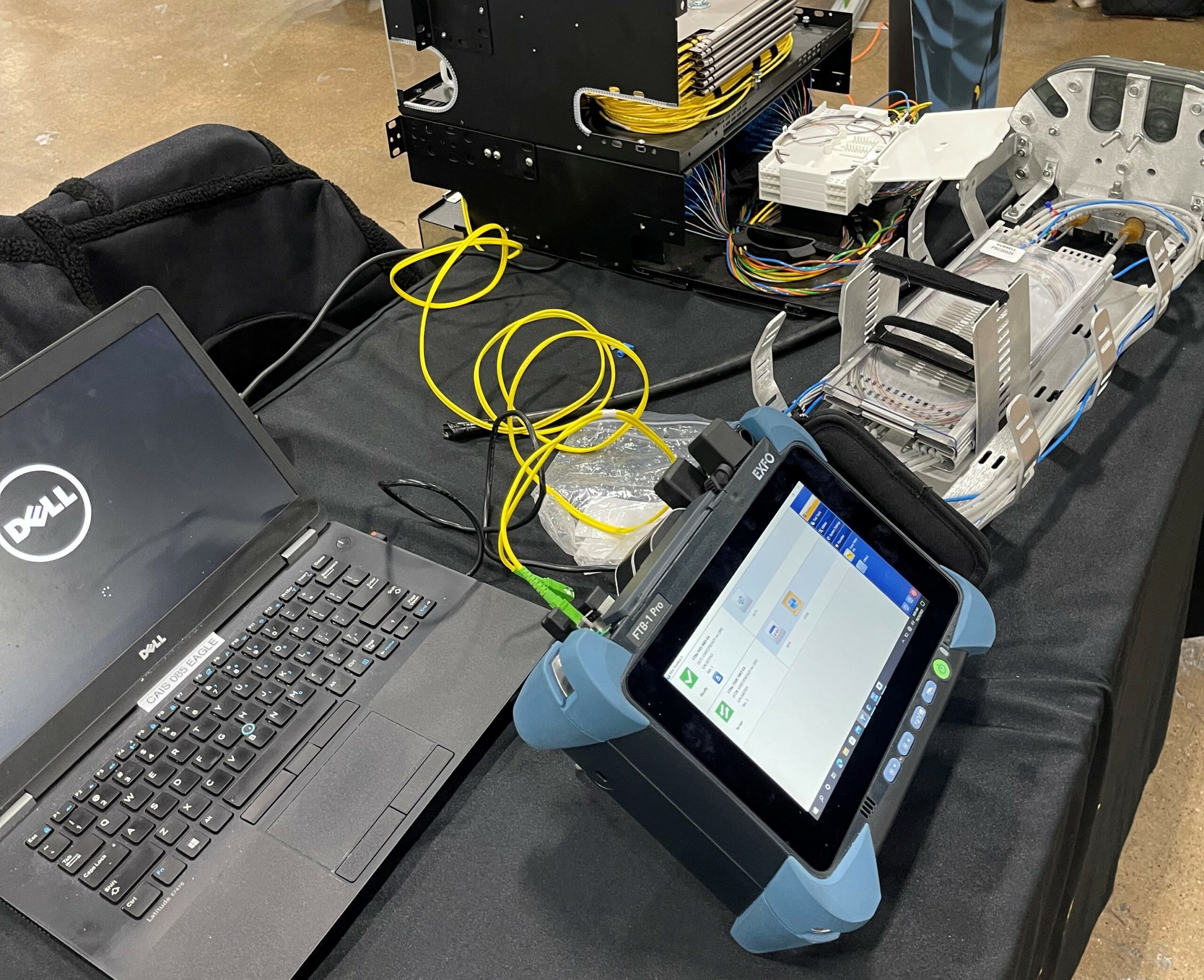
Optical testing (OTDR, insertion loss, return loss)
    • Engineers validate real-world performance by measuring attenuation across each strand, identifying splice quality, detecting macro-bends, and pinpointing reflections or faults. OTDR traces help locate events along the fiber span, while insertion and return loss testing confirm that links meet performance thresholds required for current and future bandwidth demands.
Documentation verification (comparing as-built records to actual infrastructure)
    • Teams reconcile labeling, strand counts, panel assignments, and routing diagrams with field conditions. Discrepancies such as mislabeled fibers, undocumented splices, or inaccurate pathway drawings are corrected to ensure network records reflect reality.
Path tracing from endpoint to endpoint
    • Each critical circuit is physically and logically traced to confirm continuity, routing accuracy, and proper termination. This step eliminates uncertainty around “mystery fibers” and ensures that redundancy paths and failover routes function as designed.
Compliance checks against industry standards like ANSI/TIA-568
    • The network is evaluated against recognized structured cabling and performance standards to confirm proper installation practices, testing thresholds, and labeling conventions. This reduces liability exposure and supports warranty, insurance, and regulatory requirements.

The goal? To give you a complete, accurate picture of your network so you can plan upgrades, troubleshoot issues, and avoid costly downtime.

2. Why Do I Need a Fiber Audit? My Network Seems Fine.

According to the Uptime Institute's 2025 Annual Outage Analysis, more than half of organizations report that their most recent significant outage cost over $100,000. For large enterprises, downtime can cost upwards of $14,000 per minute. And a surprising number of those outages trace back to fiber infrastructure issues that could have been caught during a routine audit.

Here are the most common reasons organizations schedule fiber audits:

Mergers or acquisitions 
    • An organization inherits a network with incomplete or outdated documentation, limiting visibility into its true configuration and condition.
Capacity planning 
    • Determine whether existing fiber infrastructure can support a planned bandwidth upgrade without performance degradation or signal loss.
Troubleshooting chronic issues 
    • Intermittent outages or ongoing performance degradation, yet internal teams cannot isolate the root cause.
Regulatory compliance 
    • Certain industries require formal documentation that verifies network integrity, performance standards, and infrastructure reliability.
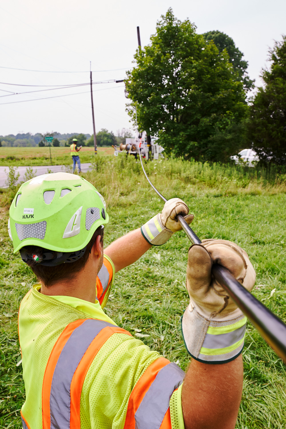
Pre-construction planning 
    • Before a dig, confirm the location and configuration of existing fiber infrastructure to prevent accidental damage and project delays.

Even when a network appears stable, an audit can reveal hidden risks such as aging splice enclosures, improper terminations, or exposed fiber vulnerable to accidental damage

3. What's the Difference Between a Fiber Audit and Regular Testing?

Regular testing (like OTDR scans or insertion loss measurements) tells how a fiber is performing right now. A fiber audit goes deeper to understand the entire lifecycle of the infrastructure.

During a fiber audit:
  • Trace every fiber path from FTP (Fiber Termination Panel) to FTP: Documenting every splice, patch panel, and cross-connect.
  • Open splice cases to verify: Splice counts, check for water intrusion, and confirm that splices match the documentation.
  • Test bidirectionally: To catch issues that only show up in one direction.
  • Update or create as-built drawings: To have accurate records moving forward.

Regular testing is reactive. Audits are proactive. And in a world where network downtime can cost thousands of dollars per minute, proactive wins every time.

4. How Long Does a Fiber Audit Take?

The timeline depends on the network’s size and complexity. A small campus environment may require about a week, while a regional telecom network spanning hundreds of miles can take several months.

Here's what affects the timeline:

Network size
    • Larger networks require more time because each fiber strand, splice point, and termination must be inspected and tested. Higher strand counts and longer pathway distances increase both field labor and data analysis requirements.
Documentation quality
    • Accurate, up-to-date records significantly accelerate the audit process because technicians can validate rather than rediscover infrastructure. 
Access restrictions 
    • Limited access to locked telecommunications rooms, underground vaults, data centers, or rooftop equipment can slow progress. 
Testing requirements
    • Basic insertion loss testing can be completed efficiently, while comprehensive OTDR analysis, including bidirectional testing and event characterization, requires more setup time, trace review, and detailed reporting.

5. What Happens After the Audit? Do I Get a Report?

At the conclusion of each audit, the engineering team delivers a comprehensive report that outlines all test results, documented findings, identified risks, and clear technical recommendations. The team provides updated as-built drawings in CAD or GIS format based on the client’s preference, ensuring all documentation reflects verified field conditions. 

The deliverables also include a detailed fiber strand inventory that identifies active strands, available dark fiber, and any damaged or compromised lines. Finally, the team presents a prioritized action plan that distinguishes between issues requiring immediate remediation, items that can be addressed over time, and lower-priority enhancements that support long-term strategic planning and capital allocation.

Clients use audit reports for:
  • Budgeting and capital planning: Knowing what needs to be replaced helps you forecast costs.
  • Vendor negotiations: Accurate documentation gives you leverage when negotiating maintenance contracts.
  • Insurance claims: If a contractor damages your fiber, you'll need proof of what was there before.

A fiber audit isn't just a box to check. It's a strategic tool that helps manage risk, plan for growth, and keep networks running smoothly.

Ready to Schedule Your Fiber Audit?

If you're dealing with outdated documentation, planning a network upgrade, or just want peace of mind that your fiber infrastructure is in good shape, Contact us today to schedule a consultation and get a custom audit plan for your network. Celerity specializes in fiber audits, OSP engineering, and fiber optic testing for organizations that can't afford downtime.

March 19, 2026

The Science Behind Fiber Characterization: Dispersion, Loss, and Return Testing Explained

Your fiber network never lies. When performance falls short of what the spec sheet promised, the root cause almost always comes down to three measurable realities: Dispersion, loss, and return.

These factors decide whether a link delivers clean 10 Gbps throughput or struggles to hold 2.5. Ignore them, and even the most expensive infrastructure underperforms.  Fiber characterization reveals how light actually moves through your cable. Experienced fiber technicians measure these parameters to expose hidden flaws, confirm design assumptions, and pinpoint exactly where performance breaks down. This work blends precision testing with real-world problem solving, and it sits at the center of every successful deployment, upgrade, or restoration.

What Is Fiber Characterization? (And Why It Matters)

Fiber characterization is the systematic testing of optical fiber to measure how it transmits light. Think of it as a health checkup for your network's arteries. Instead of blood pressure and cholesterol, you're measuring things like attenuation (signal loss), chromatic dispersion (pulse spreading), and return loss (reflected light).

Here's why it matters: fiber optic cables don't fail the way copper cables do. They degrade slowly, invisibly, and often in ways that don't trigger alarms until it's too late. A fiber link might look fine with basic testing but still cause packet loss, jitter, or intermittent outages because of hidden issues like macro-bends, splice defects, or dispersion.

Dispersion: When Light Spreads Out

Dispersion is what happens when a clean, sharp pulse of light starts to lose its shape as it travels through fiber. Think of shouting across a canyon. Your voice may start out crisp, but by the time it reaches the other side, echoes smear the sound and the words run together. Light behaves the same way in an optical fiber. As distance increases, dispersion causes light pulses to spread out and blur into one another, making it harder for the receiver to tell where one wave ends and the next begins.

One major contributor is chromatic dispersion. Light is not a single color but a narrow band of wavelengths, and each wavelength travels at a slightly different speed through glass. Over long distances, those tiny speed differences add up. The pulse stretches, much like cars entering a highway at different times. 

Chromatic dispersion is measured in picoseconds per nanometer per kilometer. In standard single-mode fiber such as SMF-28, dispersion at 1550 nanometers is about 17 ps/nm·km. That number seems small until you multiply it by distance. Over an 80-kilometer span, dispersion accumulates quickly. At 10 gigabits per second, a system can tolerate roughly 1,000 picoseconds per nanometer before errors rise sharply. Push the data rate to 40 gigabits per second, and that tolerance collapses to around 60 picoseconds per nanometer.

Polarization mode dispersion adds another layer of complexity. Light in a fiber travels in two polarization states, similar to horizontal and vertical waves. If the fiber core is not perfectly symmetrical, which can happen due to manufacturing variations, bending, or mechanical stress, those two states move at different speeds. The result is a slight timing skew that spreads the pulse even further. Unlike chromatic dispersion, PMD is random and cumulative, and it is measured in picoseconds per square root kilometer. Modern network standards recommend PMD coefficients below 0.5 ps/√km. On a 100-kilometer link, that translates to a total PMD of about 5 picoseconds. It is a tight margin, but one that high-speed optical systems depend on to maintain clean, reliable transmission.

Where Signal Loss Happens

Attenuation, often called insertion loss, is the gradual reduction in signal strength as light moves through splices and connectors. As the signal travels, a portion of the light energy is also lost to absorption within the glass, microscopic scattering, and small imperfections formed during manufacturing. This loss is unavoidable, but it must be carefully managed to keep a network stable and within its power budget.

Technicians measure attenuation in decibels per kilometer. In standard single-mode fiber such as SMF-28, loss at 1310 nanometers is typically around 0.35 dB per kilometer, while at 1550 nanometers it drops to about 0.20 dB per kilometer. That difference is why wavelength matters. Shorter wavelengths scatter more as they interact with the glass structure, while longer wavelengths travel more efficiently. This is also why long-haul and high-capacity networks favor 1550 nanometers. The signal simply goes farther with less power loss.

The fiber itself is only part of the story. Real-world attenuation adds up quickly once splices, connectors, and bends enter the equation. A poorly cleaned connector can introduce half a decibel of loss on its own. A tight bend in a cable can add another 0.3 dB without anyone noticing. When multiple small issues stack together, a link that looked fine on paper can burn through a 20 dB power budget faster than expected.

Return Testing: The Echo That Tells the Truth

Optical Return Loss, or ORL, measures how much light reflects back toward the transmitter instead of continuing down the fiber. Every time light encounters a change in refractive index, such as a connector interface, a splice point, a microscopic crack, or even a small air gap, a portion of that energy bounces backward. In a controlled system, reflections remain minimal. In a poorly installed or contaminated link, they quickly become a serious performance threat.

Technicians measure ORL in negative decibels. The more negative the value, the better the performance. A reading of negative 40 dB or lower indicates a strong link with minimal reflectance. Around negative 30 dB is generally acceptable for many systems. Once measurements approach negative 20 dB or higher, reflections become problematic and demand investigation.

Reflected light disrupts transmission because it interferes directly with the source laser. The effect resembles trying to speak clearly while someone echoes your own words back at full volume. In high-speed digital systems and especially in analog applications, that interference can distort signals, increase bit error rates, and destabilize the transmitter.

The stakes rise even higher in dense wavelength-division multiplexing (DWDM) systems. In DWDM environments, multiple wavelengths share the same fiber simultaneously. Even minor reflections can introduce crosstalk between channels, degrading overall system integrity. For 40G, 100G, and coherent optical systems, ORL testing is not optional. It is a fundamental validation step that ensures the link performs reliably under high data rates and tight optical tolerances.

Choosing the Right Fiber Characterization Test Equipment

Not all fiber test equipment delivers the same level of insight. The right tools determine whether you diagnose a problem accurately the first time or chase symptoms for weeks. Serious network validation starts with instruments that measure performance comprehensively, not just superficially.

An Optical Time-Domain Reflectometer, or OTDR, remains the foundation of fiber testing. It sends controlled light pulses down the fiber and analyzes the reflections that return. From that data, it maps splice points, connector interfaces, bends, and breaks while quantifying loss at each event. When a link fails or underperforms, the OTDR provides the visual fingerprint that pinpoints exactly where performance degrades.

A chromatic dispersion analyzer becomes essential as data rates increase. It measures dispersion across multiple wavelengths and quantifies how pulse spreading will impact transmission over distance. Networks operating at 10 gigabits per second and above rely on accurate CD measurements, particularly at both 1310 nanometers and 1550 nanometers, where dispersion behavior differs significantly.

A PMD analyzer addresses polarization mode dispersion through interferometric measurement techniques. As speeds move into 40 gigabits and coherent optical systems, PMD margins tighten dramatically. Without precise PMD data, high-speed links can appear stable during commissioning but fail unpredictably under load.

An optical return loss meter completes the picture by measuring reflections along the link and at connector interfaces. Many advanced OTDR platforms integrate ORL testing, allowing technicians to validate both attenuation and reflectance in a single workflow.

For DWDM deployments or 100G systems, they offer a strategic advantage. It evaluates attenuation, dispersion, PMD, and return loss in one coordinated pass. This approach accelerates commissioning, improves measurement consistency, and reduces the risk of overlooking subtle impairments that only surface at scale.

Fiber characterization isn't glamorous, but it's the foundation of every reliable network. Whether you're deploying a new link or troubleshooting an existing one, understanding dispersion, loss, and return testing gives you the insight you need to make smart decisions.

Contact Us

Name

1 2 34
footer-logo

Subscribe to our newsletter to stay Well Connected with Celerity Integrated Services, Inc.

Contact Us

3500 AM Drive,
Quakertown, PA 18951

P 215 538 1600
F 215 538 1602

info@nextmiletech.com

proview

© 2025 Celerity Integrated Services. Privacy Policy. Site by Smith & Howell Design Co.

Back to top Arrow