March 19, 2026

The Science Behind Fiber Characterization: Dispersion, Loss, and Return Testing Explained

Your fiber network never lies. When performance falls short of what the spec sheet promised, the root cause almost always comes down to three measurable realities: Dispersion, loss, and return.

These factors decide whether a link delivers clean 10 Gbps throughput or struggles to hold 2.5. Ignore them, and even the most expensive infrastructure underperforms.  Fiber characterization reveals how light actually moves through your cable. Experienced fiber technicians measure these parameters to expose hidden flaws, confirm design assumptions, and pinpoint exactly where performance breaks down. This work blends precision testing with real-world problem solving, and it sits at the center of every successful deployment, upgrade, or restoration.

What Is Fiber Characterization? (And Why It Matters)

Fiber characterization is the systematic testing of optical fiber to measure how it transmits light. Think of it as a health checkup for your network's arteries. Instead of blood pressure and cholesterol, you're measuring things like attenuation (signal loss), chromatic dispersion (pulse spreading), and return loss (reflected light).

Here's why it matters: fiber optic cables don't fail the way copper cables do. They degrade slowly, invisibly, and often in ways that don't trigger alarms until it's too late. A fiber link might look fine with basic testing but still cause packet loss, jitter, or intermittent outages because of hidden issues like macro-bends, splice defects, or dispersion.

Dispersion: When Light Spreads Out

Dispersion is what happens when a clean, sharp pulse of light starts to lose its shape as it travels through fiber. Think of shouting across a canyon. Your voice may start out crisp, but by the time it reaches the other side, echoes smear the sound and the words run together. Light behaves the same way in an optical fiber. As distance increases, dispersion causes light pulses to spread out and blur into one another, making it harder for the receiver to tell where one wave ends and the next begins.

One major contributor is chromatic dispersion. Light is not a single color but a narrow band of wavelengths, and each wavelength travels at a slightly different speed through glass. Over long distances, those tiny speed differences add up. The pulse stretches, much like cars entering a highway at different times. 

Chromatic dispersion is measured in picoseconds per nanometer per kilometer. In standard single-mode fiber such as SMF-28, dispersion at 1550 nanometers is about 17 ps/nm·km. That number seems small until you multiply it by distance. Over an 80-kilometer span, dispersion accumulates quickly. At 10 gigabits per second, a system can tolerate roughly 1,000 picoseconds per nanometer before errors rise sharply. Push the data rate to 40 gigabits per second, and that tolerance collapses to around 60 picoseconds per nanometer.

Polarization mode dispersion adds another layer of complexity. Light in a fiber travels in two polarization states, similar to horizontal and vertical waves. If the fiber core is not perfectly symmetrical, which can happen due to manufacturing variations, bending, or mechanical stress, those two states move at different speeds. The result is a slight timing skew that spreads the pulse even further. Unlike chromatic dispersion, PMD is random and cumulative, and it is measured in picoseconds per square root kilometer. Modern network standards recommend PMD coefficients below 0.5 ps/√km. On a 100-kilometer link, that translates to a total PMD of about 5 picoseconds. It is a tight margin, but one that high-speed optical systems depend on to maintain clean, reliable transmission.

Where Signal Loss Happens

Attenuation, often called insertion loss, is the gradual reduction in signal strength as light moves through splices and connectors. As the signal travels, a portion of the light energy is also lost to absorption within the glass, microscopic scattering, and small imperfections formed during manufacturing. This loss is unavoidable, but it must be carefully managed to keep a network stable and within its power budget.

Technicians measure attenuation in decibels per kilometer. In standard single-mode fiber such as SMF-28, loss at 1310 nanometers is typically around 0.35 dB per kilometer, while at 1550 nanometers it drops to about 0.20 dB per kilometer. That difference is why wavelength matters. Shorter wavelengths scatter more as they interact with the glass structure, while longer wavelengths travel more efficiently. This is also why long-haul and high-capacity networks favor 1550 nanometers. The signal simply goes farther with less power loss.

The fiber itself is only part of the story. Real-world attenuation adds up quickly once splices, connectors, and bends enter the equation. A poorly cleaned connector can introduce half a decibel of loss on its own. A tight bend in a cable can add another 0.3 dB without anyone noticing. When multiple small issues stack together, a link that looked fine on paper can burn through a 20 dB power budget faster than expected.

Return Testing: The Echo That Tells the Truth

Optical Return Loss, or ORL, measures how much light reflects back toward the transmitter instead of continuing down the fiber. Every time light encounters a change in refractive index, such as a connector interface, a splice point, a microscopic crack, or even a small air gap, a portion of that energy bounces backward. In a controlled system, reflections remain minimal. In a poorly installed or contaminated link, they quickly become a serious performance threat.

Technicians measure ORL in negative decibels. The more negative the value, the better the performance. A reading of negative 40 dB or lower indicates a strong link with minimal reflectance. Around negative 30 dB is generally acceptable for many systems. Once measurements approach negative 20 dB or higher, reflections become problematic and demand investigation.

Reflected light disrupts transmission because it interferes directly with the source laser. The effect resembles trying to speak clearly while someone echoes your own words back at full volume. In high-speed digital systems and especially in analog applications, that interference can distort signals, increase bit error rates, and destabilize the transmitter.

The stakes rise even higher in dense wavelength-division multiplexing (DWDM) systems. In DWDM environments, multiple wavelengths share the same fiber simultaneously. Even minor reflections can introduce crosstalk between channels, degrading overall system integrity. For 40G, 100G, and coherent optical systems, ORL testing is not optional. It is a fundamental validation step that ensures the link performs reliably under high data rates and tight optical tolerances.

Choosing the Right Fiber Characterization Test Equipment

Not all fiber test equipment delivers the same level of insight. The right tools determine whether you diagnose a problem accurately the first time or chase symptoms for weeks. Serious network validation starts with instruments that measure performance comprehensively, not just superficially.

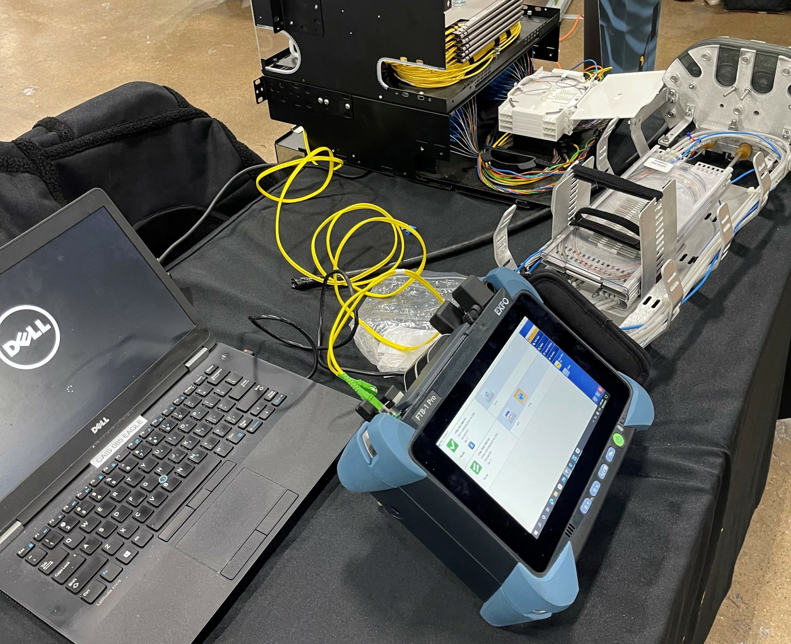
An Optical Time-Domain Reflectometer, or OTDR, remains the foundation of fiber testing. It sends controlled light pulses down the fiber and analyzes the reflections that return. From that data, it maps splice points, connector interfaces, bends, and breaks while quantifying loss at each event. When a link fails or underperforms, the OTDR provides the visual fingerprint that pinpoints exactly where performance degrades.

A chromatic dispersion analyzer becomes essential as data rates increase. It measures dispersion across multiple wavelengths and quantifies how pulse spreading will impact transmission over distance. Networks operating at 10 gigabits per second and above rely on accurate CD measurements, particularly at both 1310 nanometers and 1550 nanometers, where dispersion behavior differs significantly.

A PMD analyzer addresses polarization mode dispersion through interferometric measurement techniques. As speeds move into 40 gigabits and coherent optical systems, PMD margins tighten dramatically. Without precise PMD data, high-speed links can appear stable during commissioning but fail unpredictably under load.

An optical return loss meter completes the picture by measuring reflections along the link and at connector interfaces. Many advanced OTDR platforms integrate ORL testing, allowing technicians to validate both attenuation and reflectance in a single workflow.

For DWDM deployments or 100G systems, they offer a strategic advantage. It evaluates attenuation, dispersion, PMD, and return loss in one coordinated pass. This approach accelerates commissioning, improves measurement consistency, and reduces the risk of overlooking subtle impairments that only surface at scale.

Fiber characterization isn't glamorous, but it's the foundation of every reliable network. Whether you're deploying a new link or troubleshooting an existing one, understanding dispersion, loss, and return testing gives you the insight you need to make smart decisions.

February 15, 2026

How Celerity Trains New Fiber Techs: From Classroom to Field-Ready Expert

The fiber optic industry faces a critical challenge: 205,000 new technicians will be needed over the next five years, according to the Fiber Broadband Association. Yet nearly 70% of current fiber optic technicians are nearing retirement. This workforce gap threatens to slow the nationwide push for universal broadband access—unless companies can train new technicians quickly and effectively.

At Celerity, a family-owned fiber optic and wireless engineering firm based in Quakertown, Pennsylvania, training isn't just about filling positions. It's about building a culture of craftsmanship that transforms complete beginners into field-ready experts in months, not years.

The Celerity Training Philosophy: Craftsmanship Meets Technology

A visit to Celerity’s headquarters immediately reveals a different standard. The walls feature documentation from past projects and highlighting core values, the equipment stays organized with precision, and safety certifications remain visible and prominent. This environment reflects intentional choices rather than aesthetics.

Since launching in October 2002, Celerity has built its reputation on what the company describes as “craftsmanship in technology,” a commitment to applying disciplined, old-world skill and deep expertise to constantly evolving technical work. The organization reinforces that standard through a single, unified workforce model that cross-trains teams for fiber optic, wireless, and hybrid applications. Celerity puts every new hire through the same foundational training, regardless of eventual specialization, which establishes consistent execution across projects and builds a team that can adapt as job requirements change.

Internal culture reinforces the same forward-looking mindset. Employees describe a company that actively studies emerging shifts in the industry and pursues work that positions the team for what comes next rather than what has already become routine.

Phase 1: Classroom Foundations and Safety-First Culture

Celerity’s training program starts well before a new technician ever touches a fiber optic cable. The first phase builds a strong base of theoretical knowledge so technicians understand the systems they will work on, how network components interact, and what failure points look like in real environments. 

That technical grounding is paired with an even stronger emphasis on safety awareness, including hazard recognition, jobsite discipline, and the procedures that prevent routine tasks from turning into incidents. By establishing these fundamentals early, the program ensures technicians enter the field with the mindset and judgment required to work confidently and safely.

New trainees learn:

  • OSHA regulations and general safety standards
  • Confined space safety for working in manholes and underground vaults
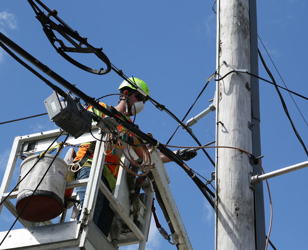
  • Height safety protocols for aerial fiber installation
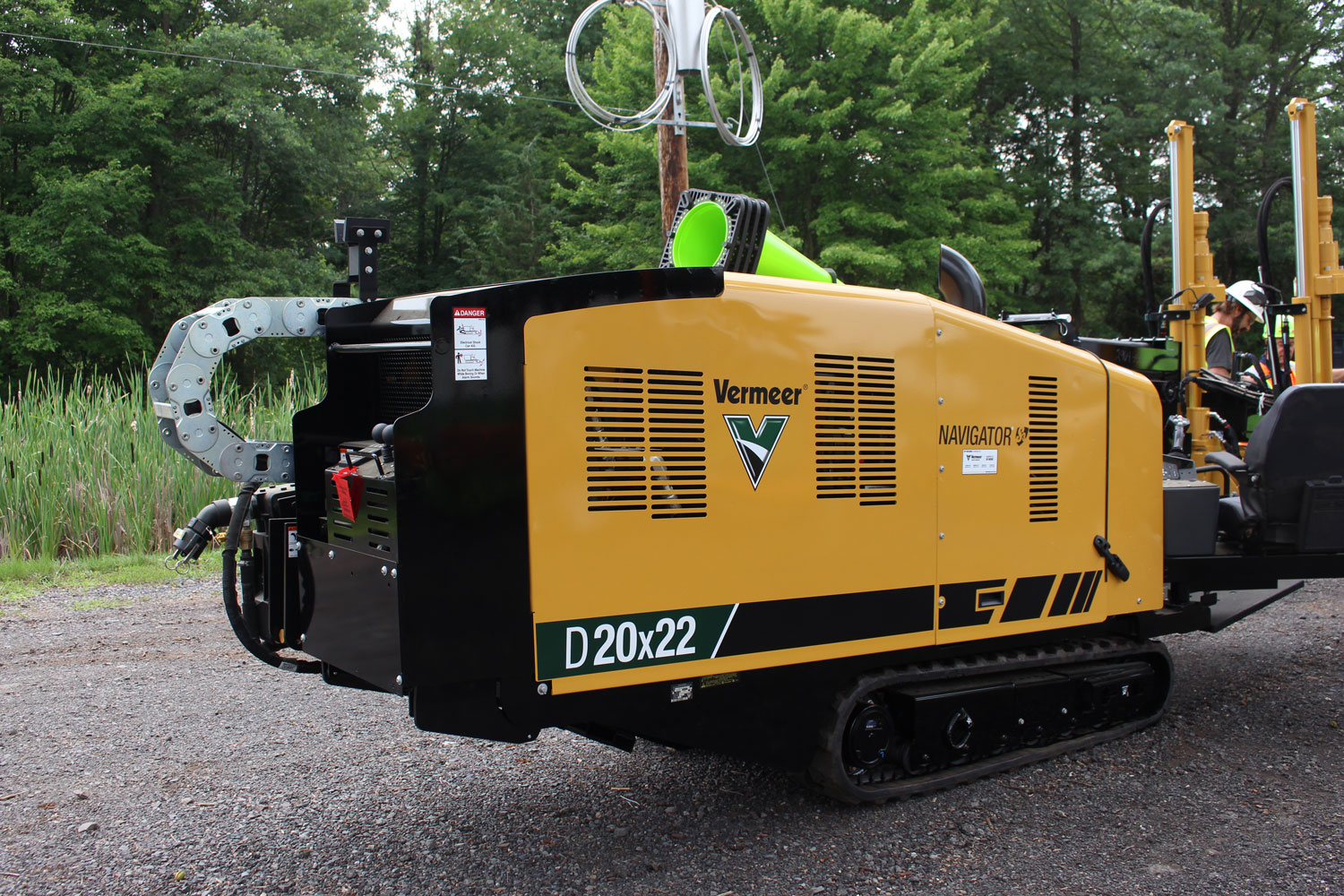
  • Equipment operation safety for heavy machinery and specialized tools
  • Emergency response procedures for field incidents

Fiber Optics Fundamentals

After trainees establish core safety protocols, the program moves into fiber optic theory to build the technical understanding required for consistent field execution. Trainees learn the differences between fiber types and geometry, including how single-mode and multi-mode fiber behave in real-world deployments and why those differences influence design and troubleshooting. They study cable structures and network architectures so they can recognize how fiber systems are built, protected, and scaled across different environments. 

The curriculum also covers light transmission principles, giving trainees a practical grasp of the physics that drive attenuation, reflectance, and signal performance. From there, trainees examine common network topologies, including FTTH, FTTB, and other deployment models, so they understand how design choices shape construction methods and service delivery. 

Throughout the theory phase, the program reinforces industry standards and documentation discipline, emphasizing that accurate records, labeling, and as-built updates protect network integrity and reduce restoration time when issues arise. 

This typically aligns with industry-standard programs like the Fiber Optic Association's CFOT certification, which requires comprehensive knowledge across fiber optic applications, installations, and testing methods.

Phase 2: Hands-On Skills Development with Real Equipment

Theory provides an essential foundation, but it does not produce job-ready technicians on its own. Real learning accelerates when trainees work directly with the tools and equipment they will use in the field. 

Celerity’s hands-on training phase builds the core technical skills every fiber technician needs by placing trainees in practical scenarios that mirror real jobsite conditions and reinforcing correct technique, quality standards, and repeatable execution.

Fiber Splicing Mastery

Fiber splicing ranks as one of the most critical skills in the industry because it permanently joins two fiber optic cables and directly affects network performance. A technician who produces inconsistent splices can introduce signal loss, create intermittent failures, and drive costly troubleshooting and rework. Celerity’s training builds splicing competency through repeatable hands-on practice that mirrors real installation and restoration conditions. 

Trainees learn fiber preparation by stripping, cleaning, and cleaving to precise specifications so the fiber end-face meets quality requirements before any splice occurs. They develop fusion splicing skills by using specialized equipment to align and fuse fibers while minimizing loss and ensuring reliable continuity. They also practice mechanical splicing for use cases where alternative joining methods make sense, then learn how to evaluate results through splice loss estimation so they can understand, measure, and reduce signal degradation. 

The training reinforces splice enclosure management as well, teaching trainees how to organize trays, label correctly, maintain bend radius, and protect completed splices so the work remains serviceable and durable over time. 

Testing and Troubleshooting

A fiber network performs only as well as it is tested, which makes testing proficiency a core focus of technician training. Trainees learn to operate visual fault locators to identify breaks, sharp bends, and continuity issues during installation and troubleshooting. They train on optical power meters to measure signal strength and verify that links meet design specifications, then progress to using OTDR equipment for advanced characterization, fault location, and documentation of fiber performance over distance. 

The program also introduces additional fiber characterization tools that help technicians confirm network health and optimize long-term reliability. This hands-on phase typically accounts for 40 to 60 percent of the total training program, with trainees repeating each task until they deliver consistent, high-quality results under realistic conditions.

Phase 3: Mentored Field Experience and Quality Standards

The final phase of training is where everything comes together. New technicians are paired with experienced mentors and deployed to actual job sites.

The Mentorship Model

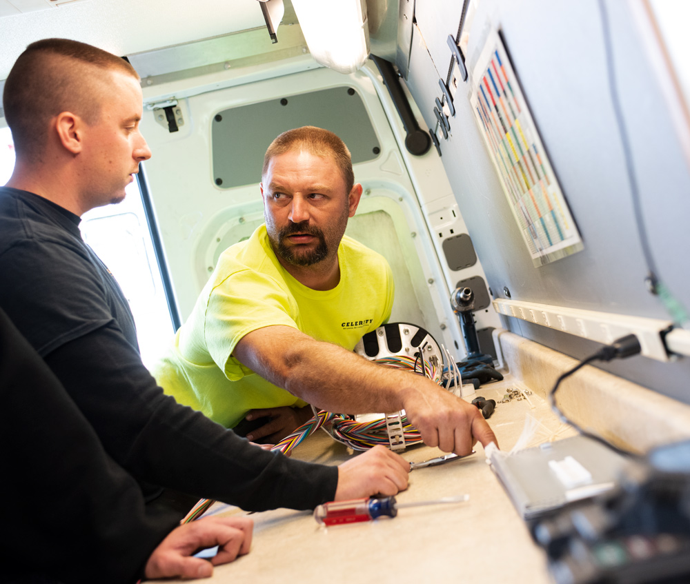
Celerity’s field training builds competence through learning by doing under close supervision. The program relies on a structured mentorship system in which senior technicians guide trainees through real-world installations, reinforce quality standards on every project, and coach problem-solving in the context of actual jobsite conditions. Mentors also model documentation discipline so trainees develop consistent habits around labeling, as-builts, and record-keeping that support faster troubleshooting and cleaner handoffs.

This mentored approach directly addresses one of the industry’s most persistent constraints, which is the time required for new hires to become reliably productive. Research from the Fiber Broadband Association indicates that it typically takes three to six months for an inexperienced hire to deliver work at a sufficient quality level. Organizations that implement structured training and mentorship programs, including approaches like Celerity’s, reduce that ramp time significantly and bring technicians up to standard faster without sacrificing quality.

Certification Pathways: CFOT and Beyond

Celerity’s training program aligns with industry-recognized certifications, with particular emphasis on the Fiber Optic Association’s Certified Fiber Optic Technician credential. The CFOT standard requires a broad understanding of fiber optic technology and real-world applications, along with demonstrated hands-on capability in splicing, termination, and testing. 

Candidates must pass a certification exam consisting of 100 multiple-choice questions, and they must achieve at least a 70 percent passing score. The credential also requires documented experience or completion of an FOA-approved training program, which ensures technicians develop both knowledge and practical competence under established training requirements. 

More than 100,000 fiber optic technicians have earned certification through FOA-approved programs worldwide, which has made CFOT one of the most widely recognized credentials in the industry.

Beyond CFOT, Celerity technicians can pursue specialized certifications in:

  • Outside Plant (OSP) installation
  • Fiber optic testing and troubleshooting
  • OPGW (Optical Ground Wire) splicing for utility applications
  • Wireless infrastructure installation

From Trainee to Expert: Career Growth at Celerity

Celerity reinforces technical quality through continuous learning and cross-training rather than treating training as a one-time event. The approach keeps technicians current as tools, standards, and deployment methods change, and it builds a more adaptable workforce that can shift between project types without sacrificing execution. Ongoing training includes new equipment and techniques as technology evolves, cross-training across specialties to expand versatility and reduce single-skill dependency, and leadership development for technicians moving into supervisory roles so they can manage crews, safety, and quality standards effectively. 

The program also supports advanced certifications for specialized applications, which helps technicians deepen expertise in higher-complexity work and ensures the organization can staff demanding projects with appropriately qualified personnel.

Career Advancement Opportunities

Celerity's training pipeline creates clear career pathways:

Entry Level:
  • Fiber Optic Technician Trainee
Intermediate:
  • Fiber Optic Splicing Technician
  • Fiber Optic Testing Technician
Advanced:
  • Senior Fiber Technician
  • Project Lead
  • Quality Inspector
Leadership:
  • Crew Foreman
  • Project Manager
  • Operations Manager

Training That Works

As the fiber optic industry experiences rapid expansion and an intensifying workforce shortage, organizations that invest in comprehensive training gain a meaningful competitive edge. Celerity’s model combines classroom-based theory, hands-on technical practice, mentored field experience, and continuous learning to demonstrate that companies can develop high-quality fiber technicians both efficiently and consistently. 

This approach shortens time to productivity compared to typical industry ramp periods, strengthens workmanship against strict specifications, and improves retention by signaling long-term investment in employee development. It also supports stronger project outcomes by building a skilled, versatile workforce that can adapt across fiber, wireless, and hybrid applications. 

For companies building fiber teams and for individuals evaluating a telecommunications career path, the takeaway remains clear: structured training that prioritizes safety, quality, and craftsmanship produces technicians who enter the field prepared to perform at a professional standard.

Contact Us

Name

1 2 36
footer-logo

Subscribe to our newsletter to stay Well Connected with Celerity Integrated Services, Inc.

Contact Us

3500 AM Drive,
Quakertown, PA 18951

P 215 538 1600
F 215 538 1602

info@nextmiletech.com

proview

© 2025 Celerity Integrated Services. Privacy Policy. Site by Smith & Howell Design Co.

Back to top Arrow